目录
1.Verilog Language
1.1 Basics
1.1.1 Simple wire
1.1.2 four wires
1.1.3 Inverter
1.1.4 AND gate
1.1.5 Norgate
1.1.6 Xnorgate
1.1.7 Wire decl
1.1.8 7458
1.2 Vectors
1.2.1 Vectors
1.2.2 Vectors in more detail
1.2.3 Vector part select
1.2.4 Bitwise operators
1.2.5 Four-input gates
1.2.6 Vector concatenation operator
1.2.7 Vector reversal 1
1.2.8 Replication operator
1.2.9 More replication
1.3 Modules Hierarchy
1.3.1 Modules
1.3.2 Connecting ports by position
1.3.3 Connecting ports by name
1.3.4 Three modules
1.3.5 Modules and vectors
1.3.6 Adder1
1.3.7 Adder2
1.3.8 Carry-select adder
1.3.9 Adder-subtractor
1.4 Procedures
1.4.1 Always blocks(combinational)
1.4.2 Always blocks(blocked)
1.4.3 If statement
1.4.4 If statement latches
1.4.5 Case statement
1.4.6 Priority encoder
1.4.7 Priority encoder with casez
1.4.8 Avoiding latches
1.5 More Verilog Features
1.5.1 Conditional temary operator
1.5.2 Reduction operators
1.5.3 Reduction : Even wider gates
1.5.4 Combinational for-loop: Vector reversal 2
1.5.5 Combinational for-loop: 255-bit population count
1.5.6 Generate for-loop:100-bit binary adder 2
1.5.7 Generate for-loop:100-digit BCD adder
2. Circuits
2.1 Combinational logic
2.1.1 Basic gates
2.1.1.1 Wire
2.1.1.2 GND
2.1.1.3 NOR
2.1.1.4 Another gate
2.1.1.5 Two gates
2.1.1.6 More logic gates
2.1.1.7 7420 chip
2.1.1.8 Truth tables
2.1.1.9 Two bit equality
2.1.1.10 Simple circuit A
2.1.1.11 Simple circuit B
2.1.1.12 Combine circuit A and B
2.1.1.13 Ring or vibrate
2.1.1.14 Thermostat
2.1.1.15 3-bit population count
2.1.1.16 Gates and Vectors
2.1.1.17 Even longer vector
2.1.2 Multiplexers
2.1.2.1 2-to-1 multiplexer
2.1.2.2 2-to-1 bus multiplexer
2.1.2.3 9-to-1 multiplexer
2.1.2.4 256-to-1 multiplexer
2.1.2.5 256-to-1 4-bit multiplexer
2.1.3 Airthmetic Circuits
2.1.3.1 Half adder
2.1.3.2 Full adder
2.1.3.3 3-bit binary adder
2.1.3.4 Adder
2.1.3.5 signed addition overflow
2.1.3.6 100-bit binary adder
2.1.3.7 4-digit BCD adder
2.1.4 Karnaugh Map to Circuit
2.1.4.1 3-variable
2.1.4.2 4-variable
2.1.4.3 4-variable
2.1.4.4 4-variable
2.1.4.5 Minimum SOP and POS
2.1.4.6 Karnaugh map
2.1.4.7 Karnaugh map
2.1.4.8 K-map implemented with a multiplexer
2.2 Sequential Logic
2.2.1 Latches and Flip-Flops
2.2.1.1 D flip-flop
2.2.1.2 D flip-flops
2.2.1.3 DFF with reset
2.2.1.4 DFF with reset value
2.2.1.5 DFF with asynchronous reset
2.2.1.6 DFF with byte enable
2.2.1.7 D Latch
2.2.1.8 DFF
2.2.1.9 DFF
2.2.1.10 DFF+gate
2.2.1.11 Mux and DFF
2.2.1.12 Mux and DFF
2.2.1.13 DFFs and gates
2.2.1.14 Create circuit from truth table
2.2.1.15 Detect an edge
2.2.1.16 Detect both edges
2.2.1.17 Edge capture register
2.2.1.18 Dual-edge triggered flip-flop
2.2.2 Counters
2.2.2.1 Four-bit binary counter
2.2.2.2 Decade counter
2.2.2.3 Decade counter again
2.2.2.4 Slow decade counter
2.2.2.5 Counter 1-12
2.2.2.6 Counter 1000
2.2.2.7 4-digit decimal counter
2.2.2.8 12-hour clock
2.2.3 Shift Registers
2.2.3.1 4-bit shift register
2.2.3.2 Left/right rotator
2.2.3.3 Left/right arithmetic shift by 1 or 8
2.2.3.4 5-bit LFSR
2.2.3.5 3-bit LFSR
2.2.3.6 32-bit LFSR
2.2.3.7 Shift register
2.2.3.8 Shift register
2.2.3.9 3-input LUT
2.2.4 More Circuits
2.2.4.1 Rule 90
2.2.4.2 Rule 110
2.2.4.3 Conway's game of life 16*16
2.2.5 Finite State Machines
2.2.5.1 Simple FSM 1 (asynchronous reset)
2.2.5.2 Simple FSM 1 (synchronous reset)
2.2.5.3 Simple FSM 2 (asynchronous reset)
2.2.5.4 Simple FSM 2 (synchronous reset)
2.2.5.5 Simple state transitions 3
2.2.5.6 Simple one-hot state transitions 3
2.2.5.7 Simple FSM 3 (asynchronous reset)
2.2.5.8 Simple FSM 3 (synchronous reset)
2.2.5.9 Design a more FSM
2.2.5.10 Lemmings 1
2.2.5.11 Lemmings 2
2.2.5.12 Lemmings 3
2.2.5.13 Lemmings 4
2.2.5.14 one-hot FSM
2.2.5.15 PS/2 packet parser
2.2.5.13 PS/2 packet parser and datapath
2.2.5.14 Serial receiver
2.2.5.15 Serial receiver and datapath
2.2.5.16 Serial receiver with pariting checking
2.2.5.17 Sequence recognition
2.2.5.18 Design a Mealy FSM
2.2.5.19 Q5a:Serial two's complementer(Moore FSM)
2.2.5.20 Q5b:Serial two's complementer(Mealy FSM)
2.2.5.21 Q3a:FSM
2.2.5.22 Q3b FSM
2.2.5.23 Q3c:FSM logic
2.2.5.24 Q6b:FSM next _state logic
2.2.5.25 Q6c:FSM one-hot next-state log
2.2.5.26 Q6:FSM
2.2.5.27 Q2a:FSM
2.2.5.28 Q2b:One-hot FSM equations
2.2.5.29 Q2a:FSM
2.2.5.30 Q2b:Another FSM
2.3 Building Large Circuits
2.3.1 couter with 1000
2.3.2 4-bit shfit register and down counter
2.3.3 FSM:Sequence 1101 recognizer
2.3.4 FSM:Enable shift register
2.3.5 FSM:The complete FSM
2.3.6 The complete timer
2.3.7 FSM:One-hot logic equations
3.Verification: Reading Simulations
3.1 Finding bugs in code
3.1.1 Mux
3.1.2 NAND
3.1.3 Mux
3.1.4 Add/Sub
3.1.5 Case Statement
3.2 Build a circuit from a simulation wavefrom
3.2.1 combinational circuit 1
3.2.2 combinational circuit 2
3.2.3 combinational circuit 3
3.2.4 combinational circuit 4
3.2.5 combinational circuit 5
3.2.6 combinational circuit 6
3.2.7 Sequential cricuit 7
3.2.8 Sequential cricuit 8
3.2.9 Sequential cricuit 9
3.2.10 Sequential cricuit 10
4.Verification: Writing Testbenches
4.1 Clock
4.2 Testbench1
4.3 AND gate
4.4 Testbench2
4.5 T flip-flop
1.Verilog Language
1.1 Basics
1.1.1 Simple wire
创建一个具有一个输入和一个输出的模块,其行为类似于电线。
与物理线不同,Verilog 中的线(和其他信号)是有方向的。仅在一个方向上的该装置的信息流,从(一般是一个)源到汇(源极还通常称为驱动器即驱动器的值到一个线)。在 Verilog “连续赋值” ( assign left_side = right_side;) 中,右侧的信号值被驱动到左侧的导线上。赋值是“连续的”,因为即使右侧的值发生变化,赋值也会一直持续。连续分配不是一次性事件。
模块上的端口也有方向(通常是输入或输出)。输入端口由模块外部的某些东西驱动,而输出端口由外部的某些东西驱动。从模块内部看,输入端口是驱动器或源,而输出端口是接收器。
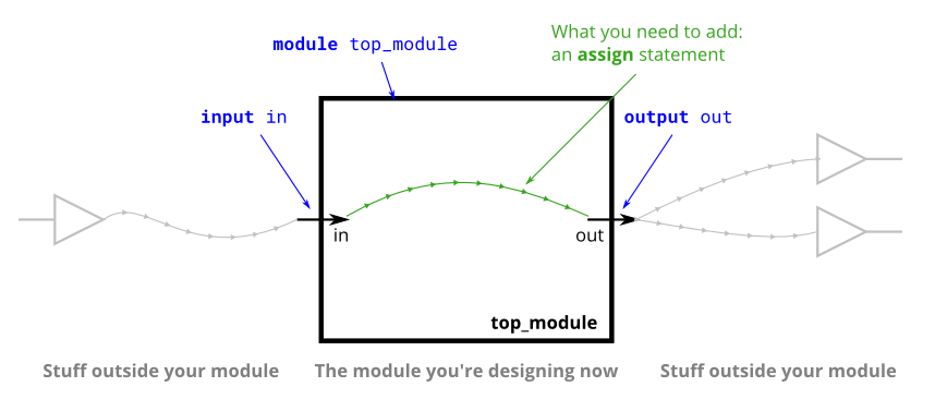
module top_module( input in, output out ); assign out = in; endmodule1.1.2 four wires
当您有多个分配语句时,它们在代码中出现的顺序无关紧要。不同于编程语言,分配语句(“连续作业”)描述了连接东西之间,而不是动作复制从一件事到另一个值。
input和output除非另有规定申报实际声明电线。写法input wire a同理input a。因此,这些assign语句不是在创建连线,而是在创建已经存在的 7 条连线之间的连接。
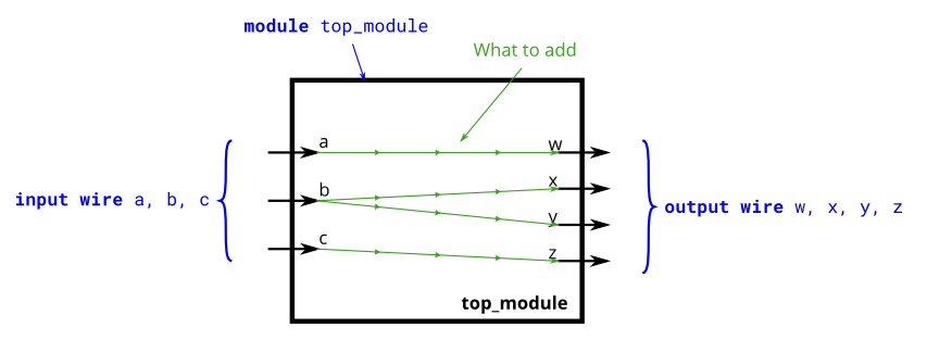
module top_module( input a,b,c, output w,x,y,z ); assign w = a; assign x = b; assign y = b; assign z = c;endmodule1.1.3 Inverter
当从电线连接in到电线时,out我们将使用逆变器(或“非门”)而不是普通电线。
Verilog 有单独的按位非 ( ~) 和逻辑非 ( !) 运算符,如 C。由于我们在这里使用一位,所以我们选择哪个并不重要。
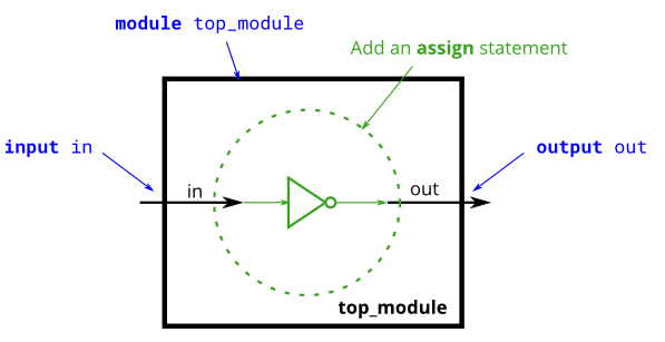
module top_module( input in, output out ); assign out = ~in;endmodule1.1.4 AND gate
Verilog 有单独的位与 ( &) 和逻辑与 ( &&) 运算符,如 C。由于我们在这里使用一位,所以我们选择哪个并不重要。
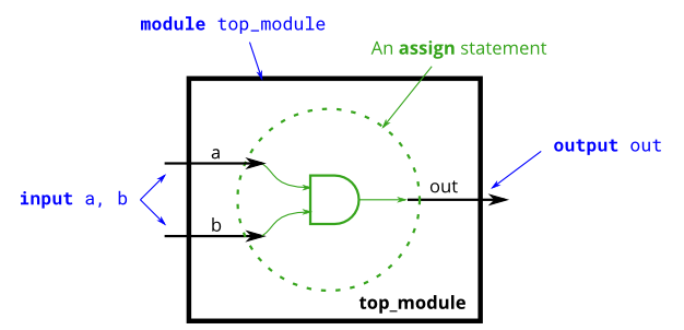
module top_module( input a, input b, output out ); assign out = a&b;endmodule1.1.5 Norgate
一个assign语句是一个连续赋值,因为只要它的任何输入永远改变,输出就会被“重新计算”,就像一个简单的逻辑门一样。
Verilog 有单独的按位或 ( |) 和逻辑或 ( ||) 运算符,如 C。由于我们在这里使用一位,所以我们选择哪个并不重要。
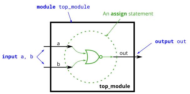
module top_module( input a, input b, output out ); assign out = ~(a|b);endmodule1.1.6 Xnorgate
按位异或运算符是^. 没有逻辑异或运算符。同或~^。
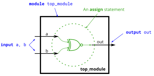
module top_module( input a, input b, output out ); assign out = a~^b;endmodule1.1.7 Wire decl
随着电路变得越来越复杂,您将需要电线将内部组件连接在一起。当你需要使用连线时,你应该在模块的主体中声明它,在它第一次使用之前的某个地方。(将来,您会遇到更多类型的信号和变量,它们也以相同的方式声明,但现在,我们将从wire类型的信号开始)。
线需要在模块内声明。从模块外部看不到它。
练习:创建两条中间线(命名为您想要的任何名称)将 AND 和 OR 门连接在一起。请注意,馈入 NOT 门的线实际上是 wire out,因此您不必在此处声明第三条线。请注意电线是如何由一个源(门的输出)驱动的,但可以馈送多个输入。
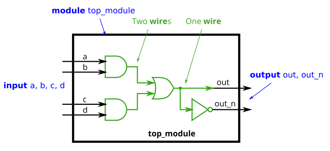
module top_module( input a, input b, input c, input d, output out, output out_n ); wire ee; wire ff; assign ee = a&b; assign ff = c&d; assign out = ee|ff; assign out_n = ~out;endmodule1.1.8 7458
7458 是具有四个与门和两个或门的芯片。这个问题比7420稍微复杂一点。
练习:创建一个与 7458 芯片功能相同的模块。它有 10 个输入和 2 个输出。您可以选择使用assign语句来驱动每条输出线,或者您可以选择声明(四)条线用作中间信号,其中每条内部线由一个与门的输出驱动。如需额外练习,请尝试两种方式。
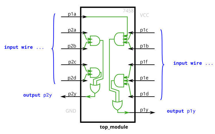
module top_module ( input p1a, p1b, p1c, p1d, p1e, p1f, output p1y, input p2a, p2b, p2c, p2d, output p2y ); wire aa; wire bb; wire cc; wire dd; assign aa = p2a&p2b; assign bb = p2c&p2d; assign p2y = aa|bb; assign cc = p1a&p1b&p1c; assign dd = p1f&p1e&p1d; assign p1y = cc|dd;endmodule1.2 Vectors
1.2.1 Vectors
向量用于使用一个名称对相关信号进行分组,以便于操作。例如,wire [7:0] w;声明一个名为w的 8 位向量,它在功能上等同于具有 8 条单独的连线。
请注意,向量的声明将维度放在向量名称之前,这与 C 语法相比是不寻常的。然而,部分选择了尺寸后,如你所期望的矢量名称。
wire [99:0] my_vector;
assign out = my_vector[10];
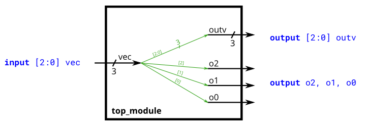
module top_module ( input wire [2:0] vec, output wire [2:0] outv, output wire o2, output wire o1, output wire o0 ); // Module body starts after module declaration assign outv = vec; assign o2 = vec[2]; assign o1 = vec[1]; assign o0 = vec[0];endmodule1.2.2 Vectors in more detail
必须声明向量:
输入 [上:下] 向量名称;
type指定向量的数据类型。这通常是wire或reg。如果您要声明输入或输出端口,则类型还可以另外包括端口类型(例如,输入或输出)。
在 Verilog 中,一旦以特定的字节顺序声明向量,它必须始终以相同的方式使用。例如,vec[0:3]在vec声明时写入wire [3:0] vec;是非法的。与字节序保持一致是一种很好的做法,因为如果将不同字节序的向量分配或一起使用,则会出现奇怪的错误。
隐式网络通常是难以检测的错误的来源。在 Verilog 中,网络类型信号可以通过assign语句或通过将未声明的内容附加到模块端口来隐式创建。隐式网络始终是一位线,如果您打算使用向量,则会导致错误。可以使用该`default_nettype none指令禁用隐式网络的创建。
练习:构建一个组合电路,将输入半字(16 位, [15:0] )拆分为低 [7:0] 和高 [15:8] 字节。
`default_nettype none // Disable implicit nets. Reduces some types of bugs.禁用隐式网络,减少某些类型的错误。module top_module( input wire [15:0] in, output wire [7:0] out_hi, output wire [7:0] out_lo ); assign out_hi = in[15:8]; assign out_lo = in[7:0];endmodule1.2.3 Vector part select
练习:一个 32 位向量可以被视为包含 4 个字节(位 [31:24]、[23:16] 等)。构建一个将反转4 字节字的字节顺序的电路。
AaaaaaaaBbbbbbbbCcccccccDdddddddd => DddddddCcccccccBbbbbbbbAaaaaaaaa
module top_module( input [31:0] in, output [31:0] out ); assign out[31:24] = in[7:0]; assign out[23:16] = in[15:8]; assign out[15:8] = in[23:16]; assign out[7:0] = in[31:24];endmodule1.2.4 Bitwise operators
使用向量时,两种运算符类型之间的区别变得很重要。两个 N 位向量之间的按位运算复制向量的每个位的运算并产生 N 位输出,而逻辑运算将整个向量视为布尔值(真 = 非零,假 = 零)和产生 1 位输出。
练习:构建一个具有两个 3 位输入的电路,用于计算两个向量的按位或、两个向量的逻辑或以及两个向量的逆 (NOT)。
b的非给out_not[5:3],a的非给out_not[2:0]。

module top_module( input [2:0] a, input [2:0] b, output [2:0] out_or_bitwise, output out_or_logical, output [5:0] out_not); assign out_or_bitwise = a|b; assign out_or_logical = a||b; assign out_not[5:3] = ~b; assign out_not[2:0] = ~a;endmodule1.2.5 Four-input gates
练习:构建一个具有四个输入的组合电路in[3:0]。
有3个输出:
out_and:4 输入与门的输出。out_or:4 输入或门的输出。out_xor:4 输入异或门的输出。module top_module( input [3:0] in, output out_and, output out_or, output out_xor); assign out_and = ∈ assign out_or = |in; assign out_xor = ^in;endmodule1.2.6 Vector concatenation operator
部分选择用于选择向量的部分。连接运算符{a,b,c}用于通过将向量的较小部分连接在一起来创建更大的向量。
{3'b111, 3'b000} => 6'b111000{1'b1, 1'b0, 3'b101} => 5'b10101{4'ha, 4'd10} => 8'b10101010 // 4'ha 和 4'd10 都是二进制的 4'b1010 连接需要知道每个组件的宽度(或者你怎么知道结果的长度?)。因此,{1, 2, 3}是非法的,并导致错误消息:unsized constants are not allowed in concatenations。
练习:给定几个输入向量,将它们连接在一起,然后将它们分成几个输出向量。有六个 5 位输入向量:a、b、c、d、e 和 f,总共 30 位输入。有四个 8 位输出向量:w、x、y 和 z,用于 32 位输出。输出应该是输入向量的串联,后跟两个1位:
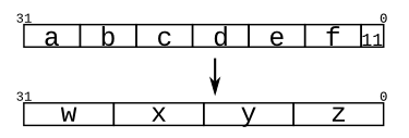
module top_module ( input [4:0] a, b, c, d, e, f, output [7:0] w, x, y, z ); assign w = {a[4:0],b[4:2]}; assign x = {b[1:0],c[4:0],d[4]}; assign y = {d[3:0],e[4:1]}; assign z = {e[0],f[4:0],2'b11};endmodule1.2.7 Vector reversal 1
练习:给定一个 8 位输入向量 [7:0],反转其位顺序。
assign out [7:0] = in[0:7]; 不起作用,因为 Verilog 不允许翻转矢量位顺序。连接运算符可以节省一些编码,允许 1 个分配语句而不是 8 个。module top_module( input [7:0] in, output [7:0] out); assign {out[0],out[1],out[2],out[3],out[4],out[5],out[6],out[7]} = in;endmodule1.2.8 Replication operator
所述并置运算符允许矢量串联起来以形成更大的载体。但有时您希望将同一事物多次连接在一起,并且执行诸如assign a = {b,b,b,b,b,b}; 之类的操作仍然很乏味。. 复制运算符允许重复一个向量并将它们连接在一起:
{num{向量}} 这种复制载体由NUM倍。num必须是一个常数。两组牙套都是必需的。
例子:
{5{1'b1}} // 5'b11111(或 5'd31 或 5'h1f){2{a,b,c}} // 与 {a,b,c,a,b,c} 相同{3'd5, {2{3'd6}}} // 9'b101_110_110。它是 101 与 // 第二个向量,它是 3'b110 的两个副本。
看到复制运算符的一个常见地方是,将较小的数字符号扩展为较大的数字,同时保留其符号值。这是通过将较小数字的符号位(最高有效位)复制到左侧来完成的。例如,将4'b 0 101 (5)符号扩展至 8 位会产生8'b 0000 0101 (5),而将4'b 1 101 (-3)符号扩展至 8 位会产生8'b 1111 1101 (-3)。
练习:构建一个将 8 位数字符号扩展为 32 位的电路。这需要连接 24 个符号位副本(即复制位 [7] 24 次),然后是 8 位数字本身。
module top_module ( input [7:0] in, output [31:0] out ); assign out = {{24{in[7]}},in[7:0]};endmodule1.2.9 More replication
练习:给定五个 1 位信号(a、b、c、d 和 e),计算 25 位输出向量中的所有 25 个成对的一位比较。如果被比较的两位相等,则输出应为 1。

如图所示,使用复制和连接运算符可以更轻松地完成此操作。
顶部向量是每个输入的 5 次重复的串联底部向量是 5 个输入的串联的 5 次重复module top_module ( input a, b, c, d, e, output [24:0] out ); assign out = ~{{5{a}},{5{b}},{5{c}},{5{d}},{5{e}}}^{{5{a,b,c,d,e}}};endmodule1.3 Modules Hierarchy
1.3.1 Modules
将电线连接到端口有两种常用的方法:按位置或按名称。
按位置将电线连接到端口的语法应该很熟悉,因为它使用类似 C 的语法。实例化模块时,端口根据模块的声明从左到右连接。
按名称将信号连接到模块的端口可以使电线保持正确连接,即使端口列表发生更改。然而,这种语法更加冗长。
mod_a instance2 ( .out(wc), .in1(wa), .in2(wb) );
上述行实例化类型的模块mod_a名为“INSTANCE2”,然后连接信号wa(模块外部)的端口命名 in1,wb到端口命名 in2,和wc到端口命名 out。
.自己模块内的(其他模块的端口)
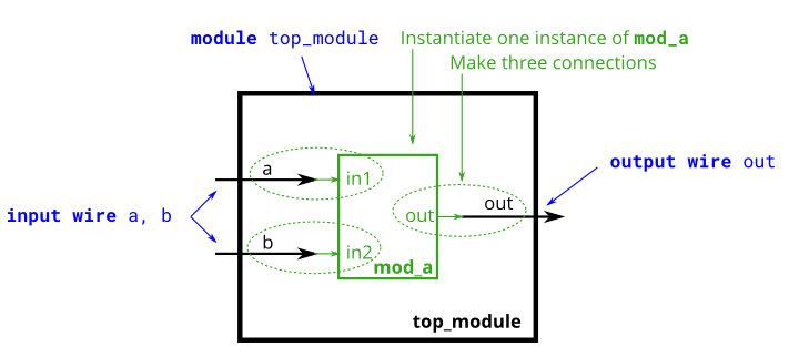
module top_module ( input a, input b, output out ); mod_a instance1(.in1(a),.in2(b),.out(out));endmodule1.3.2 Connecting ports by position
您将获得以下模块:
module mod_a ( output, output, input, input, input, input );
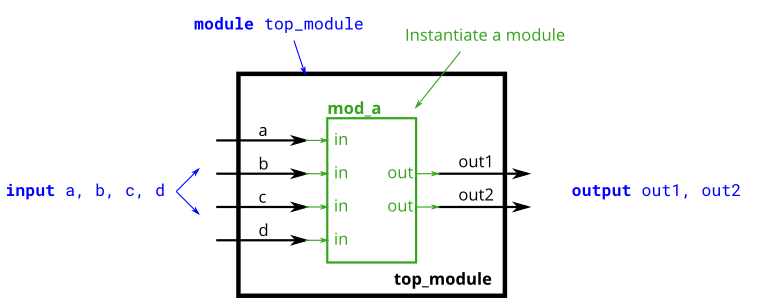
module top_module ( input a, input b, input c, input d, output out1, output out2); mod_a instance1(out1,out2,a,b,c,d);endmodule1.3.3 Connecting ports by name
module top_module ( input a, input b, input c, input d, output out1, output out2); mod_a instance1(.out1(out1),.out2(out2),.in1(a),.in2(b),.in3(c),.in4(d));endmodule1.3.4 Three modules
练习:您将获得一个my_dff具有两个输入和一个输出的模块(实现 D 触发器)。实例化其中的三个,然后将它们链接在一起以制作长度为 3 的移位寄存器。clk端口需要连接到所有实例。
提供给您的模块是: module my_dff ( input clk, input d, output q );
请注意,要建立内部连接,您需要声明一些连线。命名你的连线和模块实例时要小心:名称必须是唯一的。

module top_module ( input clk, input d, output q ); wire q1,q2; my_dff u1(.clk(clk),.d(d),.q(q1)); my_dff u2(.clk(clk),.d(q1),.q(q2)); my_dff u3(.clk(clk),.d(q2),.q(q));endmodule1.3.5 Modules and vectors
模块端口不再只是单个引脚,我们现在有带有向量作为端口的模块,您将连接线向量而不是普通线。与 Verilog 中的其他任何地方一样,端口的向量长度不必与连接到它的导线相匹配,但这会导致向量的零填充或截断。
练习:您将获得一个my_dff8具有两个输入和一个输出的模块(实现一组 8 个 D 触发器)。实例化其中的三个,然后将它们链接在一起,形成一个长度为 3 的 8 位宽移位寄存器。此外,创建一个 4 对 1 多路复用器(未提供),它根据以下内容选择输出sel[1:0]: 输入处的值d、在第一个、第二个或第三个 D 触发器之后。(本质上,sel选择延迟输入的周期数,从零到三个时钟周期。)

module top_module ( input clk, input [7:0] d, input [1:0] sel, output [7:0] q ); wire [7:0] q1,q2,q3; my_dff8 u1(.clk(clk),.d(d),.q(q1)); my_dff8 u2(.clk(clk),.d(q1),.q(q2)); my_dff8 u3(.clk(clk),.d(q2),.q(q3)); always @(*) begin case(sel) 2'b00: q = d; 2'b01: q = q1; 2'b10: q = q2; 2'b11: q = q3; default: q = {8{1'b0}}; endcase endendmodule1.3.6 Adder1
练习:您将获得一个add16执行 16 位加法的模块。实例化其中两个以创建一个 32 位加法器。一个 add16 模块计算加法结果的低 16 位,而第二个 add16 模块在接收到第一个加法器的进位后计算结果的高 16 位。您的 32 位加法器不需要处理进位(假设为 0)或进位(忽略),但内部模块需要才能正常工作。(换句话说,add16模块执行 16 位 a + b + cin,而您的模块执行 32 位 a + b)。
如下图所示将模块连接在一起。提供的模块add16具有以下声明:
module add16 ( input[15:0] a, input[15:0] b, input cin, output[15:0] sum, output cout );

module top_module( input [31:0] a, input [31:0] b, output [31:0] sum); wire [15:0] sum1; wire [15:0] sum2; wire cout_temp; add16 u1(.a(a[15:0]),.b(b[15:0]),.cin(1'b0),.sum(sum1),.cout(cout_temp)); add16 u2(.a(a[31:16]),.b(b[31:16]),.cin(cout_temp),.sum(sum2)); assign {sum} = {sum2,sum1};endmodule1.3.7 Adder2
练习:您将创建具有两个层次结构的电路。您top_module将实例化add16(提供)的两个副本,每个副本将实例化add1(您必须编写)的16 个副本。因此,您必须编写两个模块:top_module和add1.
像module_add,您将获得一个add16执行 16 位加法的模块。您必须实例化其中的两个以创建 32 位加法器。一个add16模块计算加法结果的低 16 位,而第二个add16模块计算结果的高 16 位。您的 32 位加法器不需要处理进位(假设为 0)或进位(忽略)。
全加器:sum = a ^ b ^ cin
cout = a&b | a&cin | b&cin
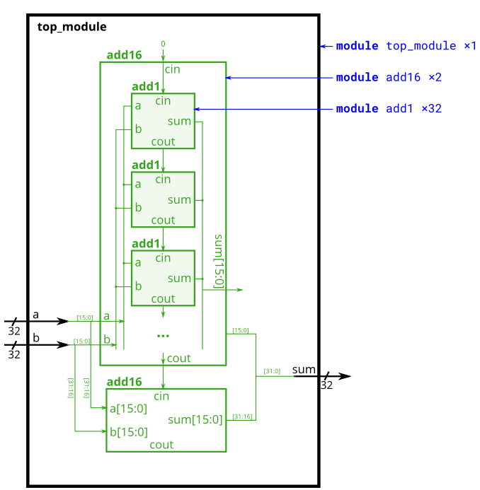
module top_module ( input [31:0] a, input [31:0] b, output [31:0] sum); wire [15:0] lowsum; wire [15:0] highsum; wire cout_temp; add16 u1 (.a(a[15:0]),.b(b[15:0]),.cin(1'b0),.sum(lowsum),.cout(cout_temp)); add16 u2 (.a(a[31:16]),.b(b[31:16]),.cin(cout_temp),.sum(highsum)); assign sum = {highsum,lowsum};endmodulemodule add1 ( input a, input b, input cin, output sum, output cout );assign sum = a^b^cin; assign cout = a&b|a&cin|b&cin;endmodule1.3.8 Carry-select adder
纹波进位加法器的一个缺点是加法器计算进位的延迟(从进位开始,在最坏的情况下)相当慢,并且第二级加法器在第一级加法器完成之前无法开始计算其进位. 这使加法器变慢。一种改进是进位选择加法器,如下所示。第一级加法器与之前相同,但我们复制第二级加法器,一个假设进位=0,一个假设进位=1,然后使用快速2对1多路复用器选择哪个结果碰巧是正确的。
练习:您将获得与add16上一个练习相同的模块,该模块将两个 16 位数字与进位相加,并产生一个进位和 16 位和。您必须使用您自己的 16 位 2 对 1 多路复用器来实例化其中的三个以构建进位选择加法器。
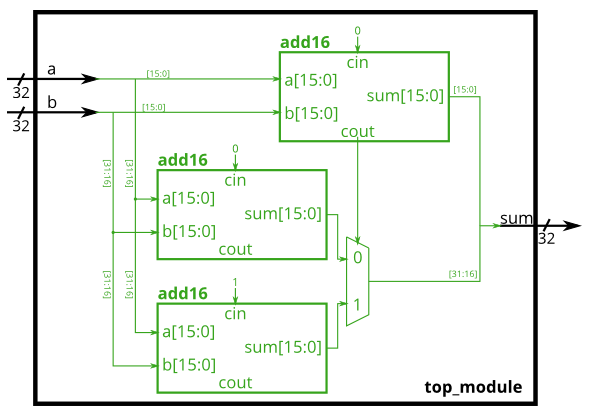
module top_module( input [31:0] a, input [31:0] b, output [31:0] sum); wire [15:0] lowsum; wire [15:0] highsum; wire [15:0] sum1; wire [15:0] sum2; wire sel; add16 u1 (.a(a[31:16]),.b(b[31:16]),.cin(1'b0),.sum(lowsum)); add16 u2 (.a(a[31:16]),.b(b[31:16]),.cin(1'b1),.sum(highsum)); add16 u3 (.a(a[15:0]),.b(b[15:0]),.cin(1'b0),.sum(sum1),.cout(sel)); always @(*) begin case(sel) 1'b0: sum2 = lowsum; 1'b1: sum2 = highsum; endcase end assign sum = {sum2,sum1};endmodule1.3.9 Adder-subtractor
加法器-减法器可以通过选择性地取反一个输入来从加法器构建,这相当于将输入反相然后加 1。最终结果是一个可以执行两种操作的电路:(a + b + 0) 和 ( a + ~b + 1)。
练习:构建下面的加减法器。
为您提供了一个 16 位加法器模块,您需要对其进行两次实例化:
module add16 ( input[15:0] a, input[15:0] b, input cin, output[15:0] sum, output cout );
每当sub为 1时,使用 32 位宽的 XOR 门来反转b输入。(这也可以视为b[31:0]与 sub 复制 32 次进行异或)。还将子输入连接到加法器的进位。
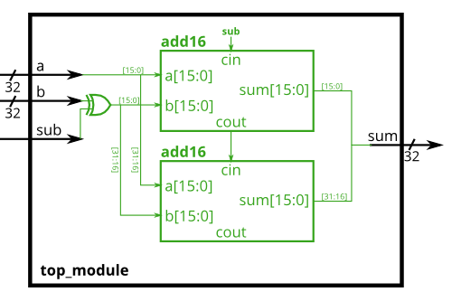
module top_module( input [31:0] a, input [31:0] b, input sub, output [31:0] sum); wire [31:0] bb; wire [15:0] lowsum; wire [15:0] highsum; wire cout_temp; assign bb = b^{32{sub}}; add16 u1 (.a(a[15:0]),.b(bb[15:0]),.cin(sub),.sum(lowsum),.cout(cout_temp)); add16 u2 (.a(a[31:16]),.b(bb[31:16]),.cin(cout_temp),.sum(highsum)); assign sum = {highsum,lowsum};endmodule1.4 Procedures
1.4.1 Always blocks(combinational)
由于数字电路是由用导线连接的逻辑门组成的,因此任何电路都可以表示为模块和赋值语句的某种组合。然而,有时这并不是描述电路的最方便的方式。过程(其中总是块是一个例子)为描述电路提供了另一种语法。
对于综合硬件,两种类型的 always 块是相关的:
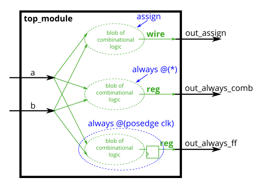
组合:总是@(*)计时:总是@(posedge clk)组合总是块等同于赋值语句,因此总有一种方法可以双向表达组合电路。选择使用哪个主要是哪个语法更方便的问题。
程序块内部代码的语法与外部代码不同。程序块具有更丰富的语句集(例如,if-then、case),不能包含连续赋值*,而且还引入了许多新的非直观的出错方式。
对于组合的 always 块,始终使用(*)的敏感度列表。明确列出信号很容易出错(如果你错过了一个),并且在硬件综合时会被忽略。如果您明确指定灵敏度列表并错过了一个信号,则合成硬件的行为仍将与指定(*) 一样,但模拟不会也不匹配硬件的行为。(在 SystemVerilog 中,使用always_comb。)
关于 wire 与 reg 的注意事项:assign 语句的左侧必须是net类型(例如,wire),而过程赋值(在 always 块中)的左侧必须是变量类型(例如,reg)。这些类型(wire vs. reg)与合成的硬件无关,只是 Verilog 用作硬件模拟语言时留下的语法。
练习:使用 assign 语句和组合 always 块构建 AND 门。
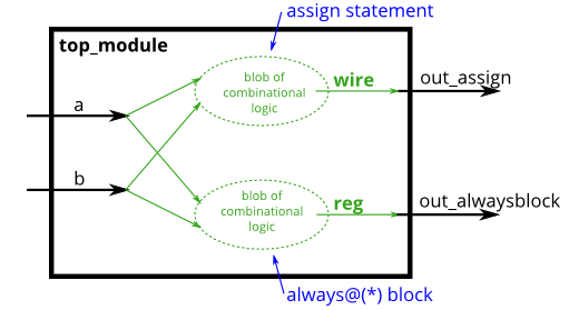
module top_module( input a, input b, output wire out_assign, output reg out_alwaysblock); assign out_assign = a&b; always @(*) begin out_alwaysblock = a&b; endendmodule1.4.2 Always blocks(blocked)
阻塞与非阻塞分配
Verilog 中有三种类型的赋值:
连续赋值(assign x = y;)。只能在不在过程中使用(“总是阻塞”)。程序阻挡分配:(X = Y; )。只能在程序内部使用。程序非阻塞赋值:( x <= y; )。只能在程序内部使用。在一个组合块,使用阻塞分配。在时钟控制的always 块中,使用非阻塞分配。完全理解为什么对硬件设计不是特别有用,并且需要很好地理解 Verilog 模拟器如何跟踪事件。不遵循此规则会导致极难发现既不确定又在模拟和合成硬件之间存在差异的错误。
练习:以三种方式构建异或门,使用分配语句、组合块和时钟块。请注意,时钟块产生的电路与其他两个不同:有一个触发器,因此输出被延迟。
module top_module( input clk, input a, input b, output wire out_assign, output reg out_always_comb, output reg out_always_ff ); assign out_assign = a^b; always @(*) begin out_always_comb = a^b; end always @(posedge clk) begin out_always_ff <= a^b; endendmodule1.4.3 If statement
一个如果语句通常会产生一个2至1多路复用器,选择如果该条件为真一个输入端,而另一个输入,如果条件为假。
always @(*) begin if (condition) begin out = x; end else begin out = y; endend
这等效于使用带有条件运算符的连续赋值:
assign out = (condition) ? x : y;
但是,程序if语句提供了一种新的出错方式。仅当总是为out分配一个值时,该电路才是组合电路。
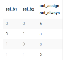
练习:构建一个在a和b之间进行选择的 2 对 1 多路复用器。选择b如果两个 sel_b1和sel_b2是真实的。否则,请选择一个。做同样的事情两次,一次使用分配语句,一次使用过程 if 语句。
module top_module( input a, input b, input sel_b1, input sel_b2, output wire out_assign, output reg out_always ); always @(*) begin if(sel_b1 == 1'b0) begin out_always = a; end else if(sel_b2 == 1'b0) begin out_always = a; end else begin out_always = b; end end assign out_assign = (sel_b1)?((sel_b2)?b:a):a;endmodule1.4.4 If statement latches
设计电路时,你必须首先想到在电路方面:
我想要这个逻辑门我想要一个具有这些输入并产生这些输出的组合逻辑块我想要一个组合的逻辑块,然后是一组触发器语法正确的代码不一定会产生合理的电路(组合逻辑 + 触发器)。通常的原因是:“在您指定的情况以外的情况下会发生什么?”。Verilog 的回答是:保持输出不变。
这种“保持输出不变”的行为意味着需要记住当前状态,从而产生一个锁存器。组合逻辑(例如逻辑门)不能记住任何状态。组合电路必须在所有条件下为所有输出分配一个值。这通常意味着您总是需要else子句或分配给输出的默认值。
练习:以下代码包含创建闩锁的不正确行为。修复错误。

module top_module ( input cpu_overheated, output reg shut_off_computer, input arrived, input gas_tank_empty, output reg keep_driving ); // always @(*) begin if (cpu_overheated) shut_off_computer = 1; else shut_off_computer = 0; end always @(*) begin if (~arrived) keep_driving = ~gas_tank_empty; else keep_driving = 0; endendmodule1.4.5 Case statement
Verilog 中的 case 语句几乎等同于将一个表达式与其他表达式进行比较的 if-elseif-else 序列。它的语法和功能不同于C 中的switch语句。
case 语句以case开头,每个“case 项”以冒号结尾。没有“switch”。每个案例项只能执行一个语句。这使得 C 中使用的“中断”变得不必要。但这意味着如果您需要多个语句,则必须使用begin ... end。允许重复(和部分重叠)案例项目。使用第一个匹配的。 C 不允许重复的案例项目。练习:如果有大量 case,case 语句比 if 语句更方便。因此,在本练习中,创建一个 6 对 1 多路复用器。当sel在 0 到 5 之间时,选择对应的数据输入。否则,输出 0。数据输入和输出均为 4 位宽。小心推断锁存器。
module top_module ( input [2:0] sel, input [3:0] data0, input [3:0] data1, input [3:0] data2, input [3:0] data3, input [3:0] data4, input [3:0] data5, output reg [3:0] out ); always@(*) begin case(sel) 3'b000: out = data0; 3'b001: out = data1; 3'b010: out = data2; 3'b011: out = data3; 3'b100: out = data4; 3'b101: out = data5; default: out = 0; endcase endendmodule1.4.6 Priority encoder
优先级编码器是一个组合电路,给定一个输入位向量时,输出第一的位置1中的向量位。例如,给定输入8'b100 1 0000的 8 位优先级编码器将输出3'd4,因为 bit[4] 是第一个高位。
练习:构建一个 4 位优先级编码器。对于这个问题,如果没有一个输入位为高(即输入为零),则输出零。请注意,一个 4 位数字有 16 种可能的组合。
module top_module ( input [3:0] in, output reg [1:0] pos ); always @(*) begin case(1) in[0]: pos = 0; in[1]: pos = 1; in[2]: pos = 2; in[3]: pos = 3; default: pos = 0; endcase endendmodule1.4.7 Priority encoder with casez
练习:为 8 位输入构建优先级编码器。给定一个 8 位向量,输出应报告向量中的第一位1。如果输入向量没有高位,则报告零。例如,输入8'b100 1 0000应该输出3'd4,因为 bit[4] 是第一个高位。如果 case 语句中的 case 项支持 don't-care 位,我们可以减少这个(减少到 9 个 case)。这就是z 的情况:它在比较中将具有值z 的位视为不关心。
case 语句的行为就好像每个项目都是按顺序检查的(实际上,它更像是生成一个巨大的真值表然后制作门)。请注意某些输入(例如4'b1111)如何匹配多个案例项目。选择第一个匹配项(因此4'b1111匹配第一项,out = 0,但不匹配任何后面的项)。
还有一个类似的casex将x和z 都视为无关。我认为在casez上使用它没有多大意义。数字?是z的同义词。所以2'bz0和2'b?0 一样module top_module ( input [7:0] in, output reg [2:0] pos ); always @(*) casez(in[7:0]) 8'bzzzzzzz1: pos = 3'b000; 8'bzzzzzz1z: pos = 3'b001; 8'bzzzzz1zz: pos = 3'b010; 8'bzzzz1zzz: pos = 3'b011; 8'bzzz1zzzz: pos = 3'b100; 8'bzz1zzzzz: pos = 3'b101; 8'bz1zzzzzz: pos = 3'b110; 8'b1zzzzzzz: pos = 3'b111; default: pos = 3'b000; endcaseendmodule1.4.8 Avoiding latches
练习:假设您正在构建一个电路来处理来自游戏的 PS/2 键盘的扫描码。鉴于收到的扫描码的最后两个字节,您需要指出是否已按下键盘上的箭头键之一。这涉及到一个相当简单的映射,它可以实现为具有四个案例的案例语句(或 if-elseif)。
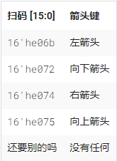
您的电路有一个 16 位输入和四个输出。构建识别这四个扫描码并断言正确输出的电路。
为避免创建锁存器,必须在所有可能的条件下为所有输出分配一个值。仅仅有一个默认情况是不够的。您必须为所有四种情况和默认情况下的所有四个输出分配一个值。这可能涉及大量不必要的输入。解决此问题的一种简单方法是在 case 语句之前为输出分配一个“默认值” :
always @(*) begin up = 1'b0; down = 1'b0; left = 1'b0; right = 1'b0; case (scancode) ... // Set to 1 as necessary. endcaseend
这种代码风格确保在所有可能的情况下为输出分配一个值(0),除非 case 语句覆盖了分配。这也意味着default: case 项变得不必要了。
提醒:逻辑合成器生成一个组合电路,其行为与代码描述的内容等效。硬件不会按顺序“执行”代码行。
module top_module ( input [15:0] scancode, output reg left, output reg down, output reg right, output reg up ); always @(*) begin up = 1'b0; down = 1'b0; left = 1'b0; right = 1'b0; case (scancode) 16'he06b: left = 1; 16'he072: down = 1; 16'he074: right = 1; 16'he075: up = 1; endcase endendmodule1.5 More Verilog Features
1.5.1 Conditional temary operator
Verilog 有一个三元条件运算符 ( ? : ) 很像 C:
(condition ? if_true : if_false)
这可用于根据条件(多路复用器!)在一行中选择两个值之一,而无需在组合 always 块内使用 if-then。
(0 ? 3 : 5) // This is 5 because the condition is false.(sel ? b : a) // A 2-to-1 multiplexer between a and b selected by sel.
always @(posedge clk) // 一个 T 型触发器。q <= toggle ? ~q : q;always @(*) // 单输入 FSM 的状态转换逻辑 case (state) A: next = w ? B : A; B: next = w ? A : B; endcaseassign out = ena ? q : 1'bz;// 三态缓冲区((sel[1:0] == 2'h0) ? a :(sel[1:0] == 2'h1) ? b: C )// 一个 3 对 1 多路复用器
练习:给定四个无符号数,求最小值。无符号数可以与标准比较运算符(a < b)进行比较。使用条件运算符制作两路最小电路,然后将其中的一些组成一个四路最小电路。您可能需要一些线向量作为中间结果。
module top_module ( input [7:0] a, b, c, d, output [7:0] min); wire [7:0] minab; wire [7:0] mincd; assign minab = (a<b)?a:b; assign mincd = (c<d)?c:d; assign min = (minab<mincd)?minab:mincd;endmodule1.5.2 Reduction operators
您已经熟悉两个值之间的按位运算,例如a & b或a ^ b。有时,您想创建一个对一个向量的所有位进行操作的宽门,例如(a[0] & a[1] & a[2] & a[3] ... ),如果向量很长。
归约运算符可以对向量的位进行 AND、OR 和 XOR,产生一位输出:
& a[3:0] // 与:a[3]&a[2]&a[1]&a[0]。相当于 (a[3:0] == 4'hf)| b[3:0] // 或:b[3]|b[2]|b[1]|b[0]。相当于 (b[3:0] != 4'h0)^ c[2:0] // 异或:c[2]^c[1]^c[0]
这些是只有一个操作数的一元运算符(类似于 NOT 运算符 ! 和 ~)。您还可以反转这些输出以创建 NAND、NOR 和 XNOR 门,例如(~& d[7:0])。
练习:当通过不完善的通道传输数据时,奇偶校验通常用作检测错误的简单方法。创建一个电路,计算 8 位字节的奇偶校验位(这将向字节添加第 9 位)。我们将使用“偶数”奇偶校验,其中奇偶校验位只是所有 8 个数据位的 XOR。
module top_module ( input [7:0] in, output parity); assign parity = ^in[7:0];endmodule1.5.3 Reduction : Even wider gates
在 [99:0] 中构建一个具有 100 个输入的组合电路。
练习:有3个输出:
out_and:100 输入与门的输出。out_or:100 输入或门的输出。out_xor:100 输入异或门的输出。module top_module( input [99:0] in, output out_and, output out_or, output out_xor ); assign out_and = &in[99:0]; assign out_or = |in[99:0]; assign out_xor = ^in[99:0];endmodule1.5.4 Combinational for-loop: Vector reversal 2
练习:给定一个 100 位输入向量 [99:0],反转其位顺序。
for 循环(在组合的 always 块或 generate 块中)在这里很有用。在这种情况下,我更喜欢组合的 always 块,因为不需要模块实例化(需要生成块)。
module top_module( input [99:0] in, output [99:0] out); integer i; always @(*) begin for(i=0;i<100;i=i+1) out[i] = in[99-i]; endendmodule1.5.5 Combinational for-loop: 255-bit population count
练习:“人口计数”电路计算输入向量中“1”的数量。为 255 位输入向量构建人口计数电路。
这么多东西要添加... for循环怎么样?
module top_module( input [254:0] in, output [7:0] out ); integer i; always @(*) begin out = 8'b00000000; for (i=0;i<255;i=i+1) begin if(in[i]==1) out = out + 8'b00000001; else out = out; end endendmodule1.5.6 Generate for-loop:100-bit binary adder 2
练习:通过实例化100个全加器来创建一个 100 位二进制波纹进位加法器。加法器将两个 100 位数字和一个进位相加,产生一个 100 位和并执行。为了鼓励您实际实例化全加器,还要输出纹波进位加法器中每个全加器的进位。cout[99] 是最后一个全加器的最终进位,也是您通常看到的进位。
有许多全加器要实例化。实例数组或生成语句将在这里有所帮助。
module top_module( input [99:0] a, b, input cin, output [99:0] cout, output [99:0] sum );genvar i; generate for(i=0;i<100;i++) begin:adder if(i==0) assign {cout[0],sum[0]} = a[0]+b[0]+cin; else assign {cout[i],sum[i]} = a[i]+b[i]+cout[i-1]; end endgenerateendmodule1.5.7 Generate for-loop:100-digit BCD adder
练习:为您提供了一个名为bcd_fadd的 BCD 一位加法器,该加法器将两个 BCD 数字和进位相加,并产生一个和和进位。
module bcd_fadd { input [3:0] a, input [3:0] b, input cin, output cout, output [3:0] sum ); 实例化 100 个bcd_fadd副本以创建一个 100 位 BCD 波纹进位加法器。您的加法器应将两个 100 位 BCD 数字(打包成 400 位向量)和一个进位相加,以产生一个 100 位和并执行。
实例数组或生成语句在这里会很有用。
module top_module( input [399:0] a, b, input cin, output cout, output [399:0] sum ); wire [99:0] cout_temp;genvar i; generate for(i=0;i<100;i++) begin:bcd_fadd if(i == 0) bcd_fadd bcd_inst(a[3:0],b[3:0],cin,cout_temp[0],sum[3:0]); else bcd_fadd bcd_inst(a[4*i+3:4*i],b[4*i+3:4*i],cout_temp[i-1],cout_temp[i],sum[4*i+3:4*i]); end assign cout = cout_temp[99]; endgenerateendmodule~*~*~*~*~*~*~*~*~*~*~*~*~*~*~*~*~*~*~*~*~*~*~*~*~*~*~*~*~*~*~*~*~*~*~*~*~*~*~*~*~*~*~*~*
分割线 2022.1.25
~*~*~*~*~*~*~*~*~*~*~*~*~*~*~*~*~*~*~*~*~*~*~*~*~*~*~*~*~*~*~*~*~*~*~*~*~*~*~*~*~*~*~*~*
2. Circuits
2.1 Combinational logic
2.1.1 Basic gates
2.1.1.1 Wire
实现以下电路:

module top_module ( input in, output out); assign out = in;endmodule2.1.1.2 GND
实现以下电路:

module top_module ( output out); assign out = 1'b0;endmodule2.1.1.3 NOR
实现以下电路:

module top_module ( input in1, input in2, output out); assign out = ~(in1|in2);endmodule2.1.1.4 Another gate
实现以下电路:

module top_module ( input in1, input in2, output out); assign out = in1&(~in2);endmodule2.1.1.5 Two gates
实现以下电路:

module top_module ( input in1, input in2, input in3, output out); assign out = (in1~^in2)^in3;endmodule2.1.1.6 More logic gates
好的,让我们尝试同时构建几个逻辑门。构建具有两个输入a和b的组合电路。
有 7 个输出,每个都有一个逻辑门驱动它:
out_and: a 和 bout_or:a 或 bout_xor: a xor bout_nand: 一个 nand bout_nor: a 或 bout_xnor: a xnor bout_anotb:a 与 b非module top_module( input a, b, output out_and, output out_or, output out_xor, output out_nand, output out_nor, output out_xnor, output out_anotb); assign out_and = a&b; assign out_or = a|b; assign out_xor = a^b; assign out_nand = ~(a&b); assign out_nor = ~(a|b); assign out_xnor = a~^b; assign out_anotb = a&(~b);endmodule2.1.1.7 7420 chip
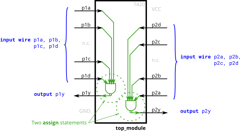
7400 系列集成电路是一系列数字芯片,每个芯片都有几个门。7420 是具有两个 4 输入与非门的芯片。
创建一个与 7420 芯片功能相同的模块。它有 8 个输入和 2 个输出。
module top_module ( input p1a, p1b, p1c, p1d, output p1y, input p2a, p2b, p2c, p2d, output p2y ); assign p1y = ~(p1a&p1b&p1c&p1d); assign p2y = ~(p2a&p2b&p2c&p2d);endmodule2.1.1.8 Truth tables
组合意味着电路的输出只是其输入的函数(在数学意义上)。这意味着对于任何给定的输入值,只有一个可能的输出值。因此,描述组合函数行为的一种方法是明确列出输入的每个可能值的输出应该是什么。
这是一个真值表。对于 N 个输入的布尔函数,有几种可能的输入组合。真值表的每一行列出一个输入组合。输出列显示每个输入值的输出应该是什么。
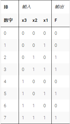
上述真值表适用于三输入一输出函数。对于 8 种可能的输入组合中的每一种,它都有 8 行,以及一个输出列。输出为 1 的输入组合有四种,输出为 0 的输入组合有四种。
假设我们要构建上述电路,但我们仅限于使用一组标准逻辑门。您将如何构建任意逻辑函数(表示为真值表)?
创建实现真值表功能的电路的一种简单方法是以乘积和形式表示该功能。乘积的总和(意思是 OR)(意思是 AND)意味着在真值表的每一行使用一个N 输入AND 门(以检测输入何时与每一行匹配),然后是一个 OR 门,它只选择那些导致'1' 输出。
对于上面的示例,如果输入与第 2行或第 3行或第 5行或第 7行匹配(这是一个 4 输入 OR 门),则输出为“1” 。如果 x3=0且x2=1且x1=0(这是一个 3 输入与门),则输入匹配第 2 行。因此,这个真值表可以通过使用 4 个 ORed 在一起的 AND 门以规范形式实现。
创建一个实现上述真值表的组合电路。
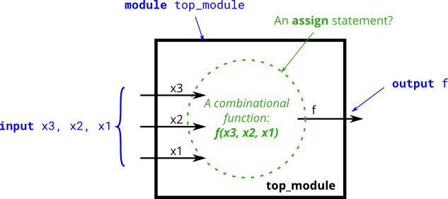
module top_module( input x3, input x2, input x1, // three inputs output f // one output); assign f = ((~x3)&x2&(~x1))|((~x3)&x2&x1)|(x3&(~x2)&x1)|(x3&x2&x1);endmodule2.1.1.9 Two bit equality
创建一个具有两个 2 位输入A[1:0]和B[1:0]的电路,并产生一个输出z。如果A = B ,则z的值应为 1 ,否则z应为 0。
module top_module ( input [1:0] A, input [1:0] B, output z ); assign z = (A==B)?1:0;endmodule2.1.1.10 Simple circuit A
模块 A 应该实现函数z = (x^y) & x。实现这个模块。
module top_module (input x, input y, output z); assign z = (x^y)&x;endmodule2.1.1.11 Simple circuit B
电路B可以用下面的仿真波形来描述:

module top_module ( input x, input y, output z ); assign z = x~^y;endmodule2.1.1.12 Combine circuit A and B
顶层设计由子电路 A 和 B 的两个实例组成,如下所示。

module top_module (input x, input y, output z); assign z = (((x^y)&x)|(x~^y))^(((x^y)&x)&(x~^y));endmodule2.1.1.13 Ring or vibrate
假设您正在设计一个电路来控制手机的振铃器和振动电机。每当电话需要从来电中振铃 ( input ring) 时,您的电路必须打开振铃器 ( output ringer = 1) 或电机 (output motor = 1 ),但不能同时打开两者。如果手机处于振动模式 ( input vibrate_mode = 1),请打开电机。否则,打开铃声。
尝试仅使用assign语句,看看您是否可以将问题描述转换为逻辑门的集合。
设计提示:在设计电路时,人们经常不得不“倒退”地考虑问题,从输出开始,然后再向输入倒退。这通常与人们思考(顺序的、命令式的)编程问题的方式相反,人们会首先查看输入,然后决定一个动作(或输出)。对于顺序程序,人们通常会认为“如果(输入是 ___ )那么(输出应该是 ___ )”。另一方面,硬件设计人员经常认为“(输出应该是 ___ )当(输入是 ___ )”。
上面的问题描述是用适合软件编程的命令式写成的(if ring then do this),所以你必须把它转换成更适合硬件实现的声明式(assign ringer = ___)。能够在两种风格之间进行思考和转换是硬件设计所需的最重要技能之一。

module top_module ( input ring, input vibrate_mode, output ringer, // Make sound output motor // Vibrate); assign ringer = ring&(~vibrate_mode); assign motor = ring&vibrate_mode;endmodule2.1.1.14 Thermostat
加热/冷却恒温器控制加热器(冬季)和空调(夏季)。实施一个可以根据需要打开和关闭加热器、空调和鼓风机的电路。
恒温器可以处于以下两种模式之一:加热 ( mode = 1) 和冷却 ( mode = 0)。在制热模式下,当天气太冷时打开加热器(too_cold = 1),但不要使用空调。在制冷模式下,空调过热时打开空调(too_hot = 1),但不要打开加热器。当加热器或空调打开时,还要打开风扇以循环空气。此外,fan_on = 1即使加热器和空调已关闭,用户也可以请求打开风扇 ( )。
尝试仅使用assign语句,看看您是否可以将问题描述转换为逻辑门的集合。
module top_module ( input too_cold, input too_hot, input mode, input fan_on, output heater, output aircon, output fan); assign heater = mode&too_cold&(~aircon); assign aircon = (~mode)&too_hot&(~heater); assign fan = heater|aircon|fan_on;endmodule2.1.1.15 3-bit population count
“人口计数”电路计算输入向量中“1”的数量。为 3 位输入向量构建人口计数电路。
module top_module( input [2:0] in, output [1:0] out ); integer i; always @(*) begin out = 2'b00; for(i=0;i<3;i=i+1) begin if(in[i]==1) out = out+2'b01; else out = out; end endendmodule2.1.1.16 Gates and Vectors
在 [3:0] 中给定一个四位输入向量。我们想知道每个位与其邻居之间的一些关系:
out_both:此输出向量的每个位都应指示相应的输入位及其左侧的邻居(较高的索引)是否都是“1” 。例如,out_both[2]应该表明in[2]和in[3]是否都为 1。由于in[3]左边没有邻居,所以答案很明显,所以我们不需要知道out_both[3 ] .out_any:此输出向量的每个位应指示相应的输入位及其右侧的邻居是否为“1”。例如,out_any[2]应该指示in[2]或in[1]是否为 1。由于in[0]右侧没有邻居,因此答案很明显,因此我们不需要知道out_any[0 ] .out_different:此输出向量的每个位都应指示相应的输入位是否与其左侧的邻居不同。例如,out_diff[2]应该指示in[2]是否与in[3]不同。对于这部分,将向量视为环绕,因此in[3]左侧的邻居是in[0]。both 、any和different输出分别使用双输入 AND、OR 和 XOR 运算。使用向量,这可以在 3 个分配语句中完成。
module top_module( input [3:0] in, output [2:0] out_both, output [3:1] out_any, output [3:0] out_different ); integer i; always @(*) begin for(i=0;i<3;i=i+1) begin out_both[i] = in[i]&in[i+1]; out_any[3-i] = in[3-i]|in[2-i]; out_different[i] = in[i]^in[i+1]; end end assign out_different[3] = in[3]^in[0];endmodule2.1.1.17 Even longer vector
在 [99:0] 中给定一个 100 位的输入向量。我们想知道每个位与其邻居之间的一些关系:
out_both:此输出向量的每个位应指示相应的输入位及其左侧的邻居是否都为“1”。例如,out_both[98]应该表明in[98]和in[99]是否都是 1。由于in[99]左边没有邻居,答案很明显,所以我们不需要知道out_both[99 ] .out_any:此输出向量的每个位应指示相应的输入位及其右侧的邻居是否为“1”。例如,out_any[2]应该指示in[2]或in[1]是否为 1。由于in[0]右侧没有邻居,因此答案很明显,因此我们不需要知道out_any[0 ] .out_different:此输出向量的每个位都应指示相应的输入位是否与其左侧的邻居不同。例如,out_diff[98]应该指示in[98]是否与in[99]不同。对于这部分,将向量视为环绕,因此in[99]左侧的邻居是in[0]。module top_module( input [99:0] in, output [98:0] out_both, output [99:1] out_any, output [99:0] out_different ); integer i; always @(*) begin for(i=0;i<99;i=i+1) begin out_both[i] = in[i]&in[i+1]; out_any[99-i] = in[99-i]|in[98-i]; out_different[i] = in[i]^in[i+1]; end end assign out_different[99] = in[99]^in[0];endmodule三段赋值语句:
module top_module( input [99:0] in, output [98:0] out_both, output [99:1] out_any, output [99:0] out_different );assign out_both = in & in[99:1];assign out_any = in[99:1] | in ;assign out_different = in ^ {in[0], in[99:1]};endmodule2.1.2 Multiplexers
2.1.2.1 2-to-1 multiplexer
创建一位宽的 2 对 1 多路复用器。当 sel=0 时,选择 a。当 sel=1 时,选择 b。
三元运算符(cond ? iftrue : iffalse)
module top_module( input a, b, sel, output out ); assign out = sel?b:a;endmodule2.1.2.2 2-to-1 bus multiplexer
创建一个 100 位宽的 2 对 1 多路复用器。当 sel=0 时,选择 a。当 sel=1 时,选择 b。
module top_module( input [99:0] a, b, input sel, output [99:0] out ); assign out = sel?b:a;endmodule2.1.2.3 9-to-1 multiplexer
创建一个 16 位宽的 9 对 1 多路复用器。sel=0 选择 a,sel=1 选择 b,等等。对于未使用的情况(sel=9 到 15),将所有输出位设置为“1”。
有了这么多选项,case 语句可能会很有用。
module top_module( input [15:0] a, b, c, d, e, f, g, h, i, input [3:0] sel, output [15:0] out ); always @(*) begin case(sel) 0: out = a; 1: out = b; 2: out = c; 3: out = d; 4: out = e; 5: out = f; 6: out = g; 7: out = h; 8: out = i; default out = {16{1'b1}}; endcase endendmodule2.1.2.4 256-to-1 multiplexer
创建一个 1 位宽、256 对 1 的多路复用器。256 个输入全部打包成一个 256 位输入向量。sel=0 应该选择in[0], sel=1 选择[1]中的位, sel=2 选择[2]中的位,等等。
有了这么多选项,case 语句就没那么有用了。向量索引可以是可变的,只要合成器可以确定被选择的位的宽度是恒定的。特别是,使用变量索引从向量中选择一位将起作用。module top_module( input [255:0] in, input [7:0] sel, output out ); assign out = in[sel];endmodule2.1.2.5 256-to-1 4-bit multiplexer
创建一个 4 位宽、256 对 1 的多路复用器。256 个 4 位输入全部打包成一个 1024 位输入向量。sel=0 应该选择[3:0]中的位, sel=1 选择[7:4]中的位, sel=2 选择[11:8]中的位等。
有了这么多选项,case 语句就没那么有用了。向量索引可以是可变的,只要合成器可以确定被选择的位的宽度是恒定的。它并不总是擅长于此。一个错误说“...不是一个常数”意味着它不能证明选择宽度是常数。特别是,in[ sel*4+3 : sel*4 ]不起作用。位切片(“索引向量部分选择”,自 Verilog-2001 以来)具有更紧凑的语法。module top_module( input [1023:0] in, input [7:0] sel, output [3:0] out ); assign out = {in[sel*4+3],in[sel*4+2],in[sel*4+1],in[sel*4]};endmodule2.1.3 Airthmetic Circuits
2.1.3.1 Half adder
创建一个半加法器。半加器将两位相加(没有进位)并产生和和进位。
module top_module( input a, b, output cout, sum ); assign cout = a&b; assign sum = a^b;endmodule2.1.3.2 Full adder
创建一个全加器。全加器将三位相加(包括进位)并产生和和进位。
module top_module( input a, b, cin, output cout, sum ); assign sum = a^b^cin; assign cout = (a&b)|(a&cin)|(b&cin);endmodule2.1.3.3 3-bit binary adder
创建 3 个实例来创建一个 3 位二进制波纹进位加法器。加法器将两个 3 位数字和一个进位相加以产生一个 3 位和并进位。为了鼓励您实际实例化全加器,还要输出纹波进位加法器中每个全加器的进位。cout[2] 是最后一个全加器的最终进位,也是您通常看到的进位。
module top_module( input [2:0] a, b, input cin, output [2:0] cout, output [2:0] sum ); add1 u1 (.a(a[0]),.b(b[0]),.cin(cin),.sum(sum[0]),.cout(cout[0])); add1 u2 (.a(a[1]),.b(b[1]),.cin(cout[0]),.sum(sum[1]),.cout(cout[1])); add1 u3 (.a(a[2]),.b(b[2]),.cin(cout[1]),.sum(sum[2]),.cout(cout[2]));endmodulemodule add1 ( input a, input b, input cin, output sum, output cout );assign sum = a^b^cin; assign cout = a&b|a&cin|b&cin;endmodule2.1.3.4 Adder
实现以下电路:

(“FA”是一个全加器)
module top_module ( input [3:0] x, input [3:0] y, output [4:0] sum); wire [2:0] cout; FA u1 (.a(x[0]),.b(y[0]),.sum(sum[0]),.cout(cout[0])); FA u2 (.a(x[1]),.b(y[1]),.cin(cout[0]),.sum(sum[1]),.cout(cout[1])); FA u3 (.a(x[2]),.b(y[2]),.cin(cout[1]),.sum(sum[2]),.cout(cout[2])); FA u4 (.a(x[3]),.b(y[3]),.cin(cout[2]),.sum(sum[3]),.cout(sum[4]));endmodulemodule FA ( input a, input b, input cin, output sum, output cout );assign sum = a^b^cin; assign cout = a&b|a&cin|b&cin;endmodulemodule top_module (input [3:0] x,input [3:0] y,output [4:0] sum);// This circuit is a 4-bit ripple-carry adder with carry-out.assign sum = x+y;// Verilog addition automatically produces the carry-out bit.// Verilog quirk: Even though the value of (x+y) includes the carry-out, (x+y) is still considered to be a 4-bit number (The max width of the two operands).// This is correct:// assign sum = (x+y);// But this is incorrect:// assign sum = {x+y};// Concatenation operator: This discards the carry-outendmodule
2.1.3.5 signed addition overflow
假设您有两个 8 位 的补码,a[7:0] 和 b[7:0]。这些数字相加产生 s[7:0]。还要计算是否发生了(有符号的)溢出。
当两个正数相加产生负结果或两个负数相加产生正结果时,会发生有符号溢出。有几种检测溢出的方法:可以通过比较输入和输出数的符号来计算,或者从位 n 和 n-1 的进位推导出。
module top_module ( input [7:0] a, input [7:0] b, output [7:0] s, output overflow); assign s = a+b; assign overflow = (a[7]&b[7]&~s[7])|(~a[7]&~b[7]&s[7]);endmodule2.1.3.6 100-bit binary adder
创建一个 100 位二进制加法器。加法器将两个 100 位数字和一个进位相加,产生一个 100 位和并执行。
module top_module( input [99:0] a, b, input cin, output cout, output [99:0] sum ); assign {cout,sum} = a+b+cin;endmodule2.1.3.7 4-digit BCD adder
为您提供了一个名为bcd_fadd的 BCD(二进制编码的十进制)一位加法器,它将两个 BCD 数字和进位相加,并产生一个和和进位。
module bcd_fadd { input [3:0] a, input [3:0] b, input cin, output cout, output [3:0] sum ); 实例化 4 个bcd_fadd副本以创建一个 4 位 BCD 波纹进位加法器。您的加法器应该将两个 4 位 BCD 数字(打包成 16 位向量)和一个进位相加,以产生一个 4 位和并执行。
5 位十进制数12345的 BCD 表示为20'h12345。这与14'd12345(即14'h3039)不同。该电路的结构就像一个二进制纹波进位加法器,除了加法器是基数 10 而不是基数 2。
module top_module( input [15:0] a, b, input cin, output cout, output [15:0] sum ); wire [2:0] c; bcd_fadd u1 (.a(a[3:0]),.b(b[3:0]),.sum(sum[3:0]),.cin(cin),.cout(c[0])); bcd_fadd u2 (.a(a[7:4]),.b(b[7:4]),.sum(sum[7:4]),.cin(c[0]),.cout(c[1])); bcd_fadd u3 (.a(a[11:8]),.b(b[11:8]),.sum(sum[11:8]),.cin(c[1]),.cout(c[2])); bcd_fadd u4 (.a(a[15:12]),.b(b[15:12]),.sum(sum[15:12]),.cin(c[2]),.cout(cout));endmodule2.1.4 Karnaugh Map to Circuit
2.1.4.1 3-variable
实现下面卡诺图描述的电路。
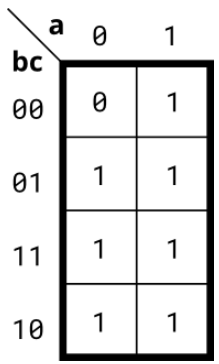
在编码之前尝试简化 k-map。尝试和积和积和形式。
module top_module( input a, input b, input c, output out ); assign out = a|b|c;endmodule2.1.4.2 4-variable
实现下面卡诺图描述的电路。
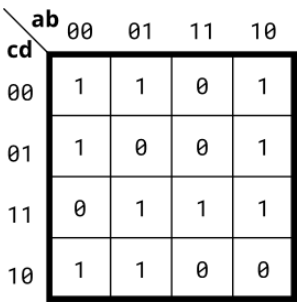
module top_module( input a, input b, input c, input d, output out ); assign out = (~b&~c)|(~a&~d)|(b&c&d)|(a&c&d);endmodule2.1.4.3 4-variable
实现下面卡诺图描述的电路。
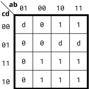
module top_module( input a, input b, input c, input d, output out ); assign out = (~b&c)|a;endmodule2.1.4.4 4-variable
实现下面卡诺图描述的电路。
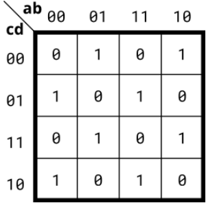
对于此函数,更改任何一个输入的值总是会反转输出。它是一个简单的逻辑函数,但不容易表达为 SOP 或 POS 形式。
module top_module( input a, input b, input c, input d, output out ); assign out = (~a&~b&~c&d)|(~a&b&~c&~d)|(a&b&~c&d)|(a&~b&~c&~d)|(~a&b&c&d)|(a&~b&c&d)|(~a&~b&c&~d)|(a&b&c&~d);endmodule2.1.4.5 Minimum SOP and POS
具有四个输入(a、b、c、d)的单输出数字系统在输入上出现 2、7 或 15 时生成逻辑 1,当输入上出现 0、1、4、5、6 、9、10、13 或 14 出现时生成逻辑 0。数字 3、8、11 和 12 的输入条件在此系统中永远不会出现。例如,7 对应于 a、b、c、d 分别设置为 0、1、1、1。
确定最小SOP形式(积之和 最小项)的输出out_sop,以及最小POS形式(和之积 最大项)的输出out_pos。
module top_module ( input a, input b, input c, input d, output out_sop, output out_pos); assign out_sop = (~a&~b&c)|(c&d); assign out_pos = c&(~b|d)&(~a|d);endmodule2.1.4.6 Karnaugh map
考虑下面卡诺图中所示 的函数f 。
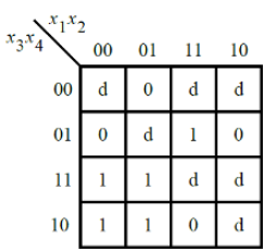
实现这个功能。d是不关心,这意味着您可以选择输出任何方便的值。
module top_module ( input [4:1] x, output f ); assign f = (~x[1]&x[3])|(x[2]&x[4]);endmodule2.1.4.7 Karnaugh map
考虑下面卡诺图中所示的函数f 。实现这个功能。
(原始考试问题要求简化 SOP 和 POS 形式的函数。)
注意卡诺图中 x[4:1] 输入位的顺序。
module top_module ( input [4:1] x, output f); assign f = (~x[1]&x[3])|(x[2]&x[3]&x[4])|(~x[2]&~x[4]);endmodule2.1.4.8 K-map implemented with a multiplexer
对于下面的卡诺图,给出使用一个 4 对 1 多路复用器和尽可能多的 2 对 1 多路复用器的电路实现,但使用尽可能少。不允许使用任何其他逻辑门,并且必须使用a和b作为多路复用器选择器输入,如下面的 4 对 1 多路复用器所示。
您只实现了标记为top_module的部分,以便整个电路(包括 4 对 1 多路复用器)实现 K-map。
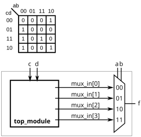
module top_module ( input c, input d, output [3:0] mux_in); assign mux_in[0] = c|d; assign mux_in[1] = 0; assign mux_in[2] = ~d; assign mux_in[3] = c&d;endmodule2.2 Sequential Logic
2.2.1 Latches and Flip-Flops
2.2.1.1 D flip-flop
D触发器是一种存储位并定期更新的电路,在时钟信号的(通常)上升沿。

当使用时钟控制的always 块时,逻辑合成器会创建 D 触发器。D触发器是“组合逻辑块后接触发器”的最简单形式,其中组合逻辑部分只是一条线。
创建一个 D 触发器。
module top_module ( input clk, input d, output reg q ); always @(posedge clk) begin q <= d; endendmodule2.2.1.2 D flip-flops
创建 8 个 D 触发器。所有 DFF 都应由clk的上升沿触发。
module top_module ( input clk, input [7:0] d, output [7:0] q); always @(posedge clk) begin q <= d; endendmodule2.2.1.3 DFF with reset
创建 8 个具有高电平有效同步复位的 D 触发器。所有 DFF 都应由clk的上升沿触发。
module top_module ( input clk, input reset, input [7:0] d, output [7:0] q); always @(posedge clk) begin if(reset) q <= 8'b00000000; else q <= d; endendmodule2.2.1.4 DFF with reset value
创建 8 个具有高电平有效同步复位的 D 触发器。触发器必须重置为 0x34 而不是零。所有 DFF 都应由clk的下降沿触发。将寄存器重置为“1”有时称为“预设”
module top_module ( input clk, input reset, input [7:0] d, output [7:0] q); always @(negedge clk) begin if(!reset) q <= d; else q <= 8'h0x34; endendmodule2.2.1.5 DFF with asynchronous reset
创建 8 个具有高电平有效异步复位的 D 触发器。所有 DFF 都应由clk的上升沿触发。
同步和异步复位触发器之间代码的唯一区别在于灵敏度列表。
module top_module ( input clk, input areset, input [7:0] d, output [7:0] q); always @(posedge clk or posedge areset) begin if(areset) q <= 8'b00000000; else q <= d; endendmodule2.2.1.6 DFF with byte enable
创建 16 个 D 触发器。有时只修改一组触发器的一部分很有用。字节使能输入控制 16 个寄存器中的每个字节是否应在该周期写入。byteena[1]控制高字节d[15:8],而byteena[0]控制低字节d[7:0]。
resetn是一个同步的低电平有效复位。
所有 DFF 都应由clk的上升沿触发。
module top_module ( input clk, input resetn, input [1:0] byteena, input [15:0] d, output [15:0] q); always @(posedge clk) begin if(resetn) begin q[15:8] <= (byteena[1])?d[15:8]:q[15:8]; q[7:0] <= (byteena[0])?d[7:0]:q[7:0]; end else q <= 16'b0; endendmodule2.2.1.7 D Latch
实现以下电路:

请注意,这是一个锁存器,因此预计会出现关于已推断锁存器的 Quartus 警告。
锁存器是电平敏感(非边沿敏感)电路,因此在一个始终块中,它们使用电平敏感灵敏度列表。但是,它们仍然是顺序元素,因此应该使用非阻塞赋值。D 锁存器在启用时就像一条线(或非反相缓冲器),在禁用时保留当前值。module top_module ( input d, input ena, output q); always @(*) begin if(ena) q <= d; endendmodule2.2.1.8 DFF
实现以下电路:
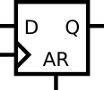
module top_module ( input clk, input d, input ar, //异步复位 output q); always @(posedge clk or posedge ar) begin if(ar) q <= 1'b0; else q <= d; endendmodule2.2.1.9 DFF
实现以下电路:
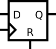
module top_module ( input clk, input d, input r, // synchronous reset 同步复位 output q); always @(posedge clk) begin if(!r) q <= d; else q <= 1'b0; endendmodule2.2.1.10 DFF+gate
实现以下电路:

module top_module ( input clk, input in, output out); always @(posedge clk) begin out <= out^in; endendmodule2.2.1.11 Mux and DFF
考虑下面的时序电路:
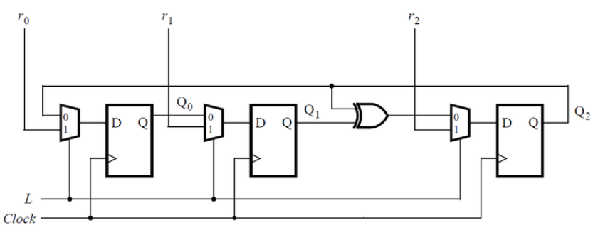
假设您要为此电路实现分层 Verilog 代码,使用其中具有触发器和多路复用器的子模块的三个实例化。为此子模块编写一个名为top_module的 Verilog 模块(包含一个触发器和多路复用器)。
module top_module (input clk,input L,input r_in,input q_in,output reg Q); always @(posedge clk) begin Q <= (L)?r_in:q_in; endendmodule2.2.1.12 Mux and DFF
考虑如下所示的n位移位寄存器电路:
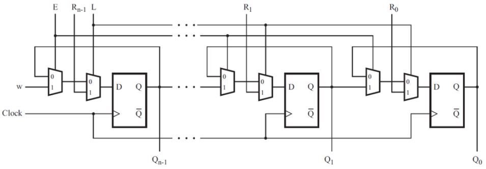
为该电路的一个阶段编写一个名为 top_module 的 Verilog 模块,包括触发器和多路复用器。
module top_module ( input clk, input w, R, E, L, output Q); always @(posedge clk) begin Q <= (L)?R:((E)?w:Q); endendmodule2.2.1.13 DFFs and gates
给定如图所示的有限状态机电路,假设 D 触发器在机器开始之前初始复位为零。
建立这个电路。
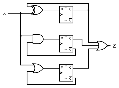
小心复位状态。确保每个 D 触发器的Q非·输出确实是其 Q 输出的倒数,即使在模拟的第一个时钟沿之前也是如此。
module top_module ( input clk, input x, output z); reg q1,q2,q3; always @(posedge clk) begin q1 <= x^q1; q2 <= x&(~q2); q3 <= x|(~q3); end assign z = ~(q1|q2|q3);endmodule2.2.1.14 Create circuit from truth table
JK 触发器具有以下真值表。实现一个只有 D 型触发器和门的 JK 触发器。注意:Qold 是正时钟沿之前 D 触发器的输出。
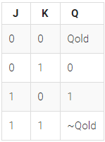
module top_module ( input clk, input j, input k, output Q); always @(posedge clk) begin case({j,k}) 2'b00: Q <= Q; 2'b01: Q <= 0; 2'b10: Q <= 1; 2'b11: Q <= ~Q; endcase endendmodule2.2.1.15 Detect an edge
对于 8 位向量中的每一位,检测输入信号何时从一个时钟周期的 0 变为下一个时钟周期的 1(类似于上升沿检测)。输出位应在发生 0 到 1 转换后的周期设置。
这里有些例子。为清楚起见,in[1] 和 pedge[1] 分别显示。

module top_module ( input clk, input [7:0] in, output [7:0] pedge); reg [7:0] temp_in; always @(posedge clk) begin temp_in <= in; pedge <= ~temp_in∈ endendmodule2.2.1.16 Detect both edges
对于 8 位向量中的每一位,检测输入信号何时从一个时钟周期变为下一个时钟周期(检测任何边沿)。输出位应在发生 0 到 1 转换后的周期设置。
这里有些例子。为清楚起见,in[1] 和 anyedge[1] 分别显示

module top_module ( input clk, input [7:0] in, output [7:0] anyedge); reg [7:0] temp_in; always @(posedge clk) begin temp_in <= in; anyedge <= temp_in^in; endendmodule2.2.1.17 Edge capture register
对于 32 位向量中的每一位,在输入信号从一个时钟周期的 1 变为下一个时钟周期的 0 时进行捕捉。“捕获”表示输出将保持为 1,直到寄存器复位(同步复位)。
每个输出位的行为类似于 SR 触发器:输出位应在 1 到 0 转换发生后的周期设置(为 1)。当复位为高电平时,输出位应在正时钟沿复位(为 0)。如果上述两个事件同时发生,则重置优先。在下面示例波形的最后 4 个周期中,“reset”事件比“set”事件早一个周期发生,因此这里不存在冲突。
在下面的示例波形中,为清楚起见,reset、in[1] 和 out[1] 再次分别显示。
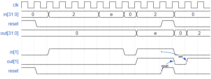
module top_module ( input clk, input reset, input [31:0] in, output [31:0] out); reg [31:0] temp_in; always @(posedge clk) begin temp_in <= in; if(reset) out <= 32'b0; else out <= temp_in&~in|out; endendmodule2.2.1.18 Dual-edge triggered flip-flop
您熟悉在时钟上升沿或时钟下降沿触发的触发器。在时钟的两个边沿触发双边触发触发器。但是,FPGA 没有双边触发触发器,并且始终不接受 @(posedge clk 或 negedge clk)作为合法的敏感度列表。
构建一个功能类似于双边触发触发器的电路:

(注意:它不一定完全等效:触发器的输出没有毛刺,但模拟这种行为的更大组合电路可能会。但我们将在这里忽略这个细节。)
您无法在 FPGA 上创建双边触发触发器。但是您可以同时创建正沿触发和负沿触发触发器。这个问题是一个中等难度的电路设计问题,但只需要基本的 Verilog 语言特性。(这是电路设计问题,而不是编码问题。)在尝试编码之前先用手画出电路图可能会有所帮助。module top_module ( input clk, input d, output q); reg q1,q2; always @(posedge clk) begin q1 <= d; end always @(negedge clk) begin q2 <= d; end assign q = clk?q1:q2;endmodule2.2.2 Counters
2.2.2.1 Four-bit binary counter
构建一个从 0 到 15(含)计数的 4 位二进制计数器,周期为 16。复位输入是同步的,应将计数器复位为 0。

module top_module ( input clk, input reset, // Synchronous active-high reset output [3:0] q); always @(posedge clk) begin if(!reset) q <= q+1'b1; else q <= 4'b0; endendmodule2.2.2.2 Decade counter
构建一个从 0 到 9(含)计数的十进制计数器,周期为 10。复位输入是同步的,应将计数器复位为 0。

module top_module ( input clk, input reset, // Synchronous active-high reset output [3:0] q); always @(posedge clk) begin if(reset || q>=4'd9) q <= 4'b0; else q <= q+1'b1; endendmodule2.2.2.3 Decade counter again
制作一个从 1 到 10 的十进制计数器,包括 1 到 10。复位输入是同步的,应将计数器复位为 1。

module top_module ( input clk, input reset, output [3:0] q); initial q = 4'b1; always @(posedge clk) begin if(reset || q>=4'd10) q <= 4'b1; else q <= q+1'b1; endendmodule2.2.2.4 Slow decade counter
构建一个从 0 到 9 计数的十进制计数器,周期为 10。复位输入是同步的,应该将计数器复位为 0。我们希望能够暂停计数器,而不是总是在每个时钟周期递增,所以slowena输入指示计数器何时应该增加。
这是一个带有启用控制信号的常规十进制计数器

module top_module ( input clk, input slowena, input reset, output [3:0] q); always @(posedge clk) begin if(reset) q <= 4'b0; else if(slowena) begin if(q>=4'd9) q <= 4'b0; else q <= q+1'b1; end else q <= q; endendmodule2.2.2.5 Counter 1-12
设计一个具有以下输入和输出的 1-12 计数器:
复位同步高电平有效复位,强制计数器为 1启用设置高以使计数器运行Clk正边沿触发时钟输入Q[3:0]计数器的输出c_enable, c_load, c_d[3:0]控制信号进入提供的 4 位计数器,因此可以验证正确的操作。您有以下可用组件:
下面的 4 位二进制计数器 ( count4 ),它具有启用和同步并行加载输入(加载的优先级高于启用)。count4模块提供给您。在你的电路中实例化它。逻辑门c_enable 、c_load和c_d输出是分别进入内部计数器的enable、load和d输入的信号。它们的目的是允许检查这些信号的正确性。
module top_module ( input clk, input reset, input enable, output [3:0] Q, output c_enable, output c_load, output [3:0] c_d); assign c_enable = enable; assign c_load = ((Q >= 4'd12)&&(enable == 1'b1))|reset; assign c_d = c_load?4'd1:4'd0; count4 the_counter (clk, c_enable, c_load, c_d , Q);endmodule2.2.2.6 Counter 1000
从 1000 Hz 时钟导出一个称为OneHertz的 1 Hz 信号,该信号可用于驱动一组小时/分钟/秒计数器的启用信号,以创建数字挂钟。由于我们希望时钟每秒计数一次,因此OneHertz信号必须每秒准确地断言一个周期。使用模 10 (BCD) 计数器和尽可能少的其他门构建分频器。还要从您使用的每个 BCD 计数器输出使能信号(c_enable[0] 为最快的计数器,c_enable[2] 为最慢的)。
为您提供以下 BCD 计数器。Enable必须为高电平才能使计数器运行。复位是同步的并设置为高以强制计数器为零。电路中的所有计数器必须直接使用相同的 1000 Hz 信号。
module top_module ( input clk, input reset, output OneHertz, output [2:0] c_enable); wire [3:0] one,ten,hundred; assign c_enable = {one == 4'd9&&ten == 4'd9,one == 4'd9,1'b1}; assign OneHertz = one == 4'd9&&ten == 4'd9&&hundred == 4'd9; bcdcount counter0 (clk, reset, c_enable[0],one); bcdcount counter1 (clk, reset, c_enable[1],ten); bcdcount counter2 (clk, reset, c_enable[2],hundred);endmodule2.2.2.7 4-digit decimal counter
构建一个 4 位 BCD(二进制编码的十进制)计数器。每个十进制数字使用 4 位编码:q[3:0] 是个位,q[7:4] 是十位等。对于数字 [3:1],还输出一个使能信号,指示每个前三位应递增。
您可能想要实例化或修改一些一位十进制计数器。
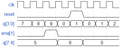
module top_module ( input clk, input reset, // Synchronous active-high reset output [3:1] ena, output [15:0] q); reg [3:0] one; reg [3:0] ten; reg [3:0] hundred; reg [3:0] thousand; always @(posedge clk) begin if(reset || one==4'd9) one <= 4'b0; else one <= one+1'b1; end always @(posedge clk) begin if(reset || ((one == 4'd9)&&(ten == 4'd9))) ten <= 4'b0; else if(one == 4'd9) begin ten <= ten+1'b1; end end always @(posedge clk) begin if(reset || ((one == 4'd9)&&(ten == 4'd9)&&(hundred == 4'd9))) hundred <= 4'b0; else if((one == 4'd9)&&(ten == 4'd9)) hundred <= hundred+1'b1; end always @(posedge clk) begin if(reset || ((one == 4'd9)&&(ten == 4'd9)&&(hundred == 4'd9)&&(thousand == 4'd9))) thousand <= 4'b0; else if((one == 4'd9)&&(ten == 4'd9)&&(hundred == 4'd9)) thousand <= thousand+1'b1; end assign q = {thousand,hundred,ten,one}; assign ena[1] = (one == 4'd9)?1'b1:1'b0; assign ena[2] = ((one == 4'd9)&&(ten == 4'd9))?1'b1:1'b0; assign ena[3] = ((one == 4'd9)&&(ten == 4'd9)&&(hundred == 4'd9))?1'b1:1'b0;endmodule2.2.2.8 12-hour clock
创建一组适合用作 12 小时制的计数器(带有上午/下午指示器)。您的计数器由快速运行的clk计时,只要您的时钟应该增加(即每秒一次),就会 在ena上显示一个脉冲。
reset将时钟重置为 12:00 AM。pm对于 AM 为 0,对于 PM 为 1。hh、mm和ss是两个BCD(二进制编码的十进制)数字,分别表示小时 (01-12)、分钟 (00-59) 和秒 (00-59)。重置的优先级高于启用,即使未启用也可能发生。
以下时序图显示了从上午 11:59:59到下午 12:00:00的翻转行为以及同步复位和启用行为。
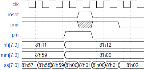
请注意, 11:59:59 PM提前到12:00:00 AM,12:59:59 PM提前到01:00:00 PM。没有 00:00:00。
module top_module( input clk, input reset, input ena, output pm, output [7:0] hh, output [7:0] mm, output [7:0] ss); reg pm_temp; reg [3:0] ss_one; reg [3:0] ss_ten; reg [3:0] mm_one; reg [3:0] mm_ten; reg [3:0] hh_one; reg [3:0] hh_ten; wire pm_ding; always @(posedge clk) begin if(reset) begin ss_one <= 4'b0; end else if(ena) begin if(ss_one == 4'd9) ss_one <= 4'b0; else ss_one <= ss_one+1'b1; end end always @(posedge clk) begin if(reset) begin ss_ten <= 4'b0; end else if((ena)&&(ss_one == 4'd9)) begin if(ss_ten == 4'd5) ss_ten <= 4'b0; else ss_ten <= ss_ten+1'b1; end end always @(posedge clk) begin if(reset) begin mm_one <= 4'b0; end else if((ena)&&(ss_one == 4'd9)&&(ss_ten == 4'd5)) begin if(mm_one == 4'd9) mm_one <= 4'b0; else mm_one <= mm_one+1'b1; end end always @(posedge clk) begin if(reset) begin mm_ten <= 4'b0; end else if((ena)&&(ss_one == 4'd9)&&(ss_ten == 4'd5)&&(mm_one == 4'd9)) begin if(mm_ten == 4'd5) mm_ten <= 4'b0; else mm_ten <= mm_ten+1'b1; end end always @(posedge clk) begin if(reset) begin hh_one <= 4'd2; end else if((ena)&&(ss_one == 4'd9)&&(ss_ten == 4'd5)&&(mm_one == 4'd9)&&(mm_ten == 4'd5)) begin if(hh_one == 4'd9) hh_one <= 4'b0; else if((hh_one == 4'd2)&&(hh_ten == 4'd1)) begin hh_one <= 4'b1; end else hh_one <= hh_one+1'b1; end end always @(posedge clk) begin if(reset) begin hh_ten <= 4'd1; end else if((ena)&&(ss_one == 4'd9)&&(ss_ten == 4'd5)&&(mm_one == 4'd9)&&(mm_ten == 4'd5)) begin if((hh_one == 4'd2)&&(hh_ten == 4'd1)) hh_ten <= 4'b0; else if(hh_one == 4'd9) begin hh_ten <= hh_ten+1'b1;; end end end always @(posedge clk) begin if(reset) begin pm_temp <= 1'b0; end else if(pm_ding) begin pm_temp <= ~pm_temp; end end assign pm_ding = (hh_ten == 4'd1)&&(hh_one == 4'd1)&&(ena)&&(ss_one == 4'd9)&&(ss_ten == 4'd5)&&(mm_one == 4'd9)&&(mm_ten == 4'd5); assign ss = {ss_ten,ss_one}; assign mm = {mm_ten,mm_one}; assign hh = {hh_ten,hh_one}; assign pm = pm_temp;endmodule2.2.3 Shift Registers
2.2.3.1 4-bit shift register
构建一个 4 位移位寄存器(右移),具有异步复位、同步加载和启用。
areset:将移位寄存器重置为零。load :用data[3:0]加载移位寄存器而不是移位。ena:右移(q[3]变为零,q[0]移出并消失)。q:移位寄存器的内容。如果load和ena输入都被置位 (1),则load输入具有更高的优先级。
module top_module( input clk, input areset, // async active-high reset to zero input load, input ena, input [3:0] data, output reg [3:0] q); always @(posedge clk or posedge areset) begin if(areset) begin q <= 4'b0; end else if(load)begin q <= data; end else if(ena)begin q <= {1'b0,q[3:1]}; end else q <= q; endendmodule2.2.3.2 Left/right rotator
构建一个 100 位左/右旋转器,具有同步加载和左/右使能。与丢弃移出位并移入零的移位器不同,旋转器从寄存器的另一端移入移出的位。如果启用,旋转器会旋转位并且不会修改/丢弃它们。
load :用data[99:0]加载移位寄存器而不是旋转。ena[1:0]:选择是否旋转以及旋转的方向。 2'b01向右旋转一位2'b10向左旋转一位2'b00和2'b11不旋转。q : 旋转器的内容。module top_module( input clk, input load, input [1:0] ena, input [99:0] data, output reg [99:0] q); always @(posedge clk) begin if(load)begin q <= data; end else if(ena == 2'b01)begin q <= {q[0],q[99:1]}; end else if(ena == 2'b10)begin q <= {q[98:0],q[99]}; end else q <= q; endendmodule2.2.3.3 Left/right arithmetic shift by 1 or 8
构建一个 64 位算术移位寄存器,同步加载。移位器可以向左和向右移动 1 位或 8 位位置,由数量选择。
算术右移移位寄存器中数字的符号位(在这种情况下为q[63] ),而不是逻辑右移所完成的零。考虑算术右移的另一种方法是,它假设被移动的数字是有符号的并保留符号,因此算术右移将带符号的数字除以 2 的幂。
逻辑左移和算术左移没有区别。
load :用data[63:0]加载移位寄存器而不是移位。ena : 选择是否换档。amount:选择要移动的方向和量。 2'b00:左移 1 位。2'b01:左移 8 位。2'b10:右移 1 位。2'b11:右移 8 位。q:移位器的内容。5 位数11000算术右移 1 是11100,而逻辑右移将产生01100。
类似地,5 位数字01000算术右移 1 是00100,逻辑右移会产生相同的结果,因为原始数字是非负数。
module top_module( input clk, input load, input ena, input [1:0] amount, input [63:0] data, output reg [63:0] q); always @(posedge clk) begin if(load)begin q <= data; end else begin if(ena) begin case(amount) 2'b00: q <= {q[62:0],1'b0}; 2'b01: q <= {q[55:0],8'b0}; 2'b10: q <= {q[63],q[63:1]}; 2'b11: q <= {{8{q[63]}},q[63:8]}; endcase end else q <= q; end end endmodule2.2.3.4 5-bit LFSR
线性反馈移位寄存器是一种移位寄存器,通常带有几个异或门来产生移位寄存器的下一个状态。伽罗瓦 LFSR 是一种特殊的安排,其中带有“抽头”的位位置与输出位进行异或运算以产生其下一个值,而没有抽头移位的位位置。如果仔细选择抽头位置,则可以将 LFSR 设置为“最大长度”。n 位的最大长度 LFSR 在重复之前循环通过 2 的n次方-1 个状态(永远不会达到全零状态)。
下图显示了一个 5 位最大长度的 Galois LFSR,在位位置 5 和 3 处具有抽头。(抽头位置通常从 1 开始编号)。请注意,为了保持一致性,我在位置 5 处绘制了 XOR 门,但 XOR 门输入之一是 0。

构建这个 LFSR。复位应将 LFSR 复位为 1 。
从 1 开始的前几个状态是00001 , 10100 , 01010 , 00101 , ... LFSR 应该在返回00001之前循环通过 31 个状态。
module top_module( input clk, input reset, // Active-high synchronous reset to 5'h1 output [4:0] q); always @(posedge clk) begin if(!reset)begin q[0] <= q[1]; q[1] <= q[2]; q[2] <= q[3]^q[0]; q[3] <= q[4]; q[4] <= q[0]^1'b0; end else q <= 5'h1; endendmodule2.2.3.5 3-bit LFSR
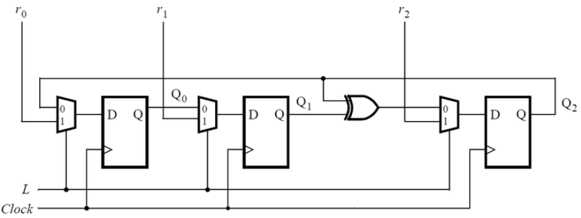
为此时序电路编写 Verilog 代码(子模块可以,但顶层必须命名为top_module)。假设您要在 DE1-SoC 板上实现电路。将R输入连接到SW开关,将 Clock 连接到KEY[0],并将L连接到KEY[1]。将Q输出连接到红灯LEDR。
该电路是线性反馈移位寄存器(LFSR) 的一个示例。最大周期 LFSR 可用于生成伪随机数,因为它在重复之前循环通过 2 的n次方-1 个组合。全零组合不会出现在此序列中。
module top_module (input [2:0] SW, // Rinput [1:0] KEY, // L and clkoutput [2:0] LEDR); // Q always @(posedge KEY[0]) begin if(KEY[1])begin LEDR[2] <= SW[2]; LEDR[1] <= SW[1]; LEDR[0] <= SW[0]; end else begin LEDR[2] <= LEDR[2]^LEDR[1]; LEDR[1] <= LEDR[0]; LEDR[0] <= LEDR[2]; end endendmodule2.2.3.6 32-bit LFSR
在位位置 32、22、2 和 1 处构建具有抽头的 32 位 Galois LFSR。
这足够长,以至于您想要使用向量,而不是 32 个 DFF 实例。
module top_module( input clk, input reset, // Active-high synchronous reset to 32'h1 output [31:0] q); always @(posedge clk) begin if(!reset)begin q[31] <= q[0]^1'b0; q[21] <= q[22]^q[0]; q[1] <= q[2]^q[0]; q[0] <= q[1]^q[0]; q[20:2] <= q[21:3]; q[30:22] <= q[31:23]; end else q <= 32'h1; endendmodule2.2.3.7 Shift register
实现以下电路:

module top_module ( input clk, input resetn, // synchronous reset input in, output out); reg [2:0] q; always @(posedge clk) begin if(resetn)begin {out,q[2:0]} <= {q[2:0],in}; end else {out,q} <= 4'b0; endendmodule2.2.3.8 Shift register
考虑如下所示 的n位移位寄存器电路:
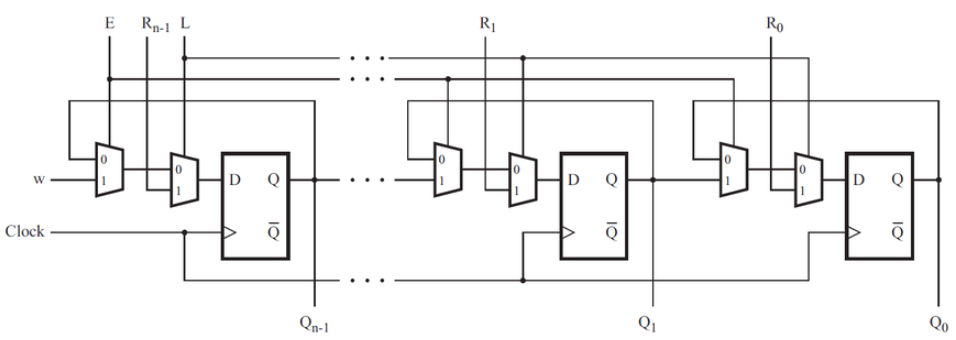
假设n = 4 ,为移位寄存器编写顶层 Verilog 模块(名为 top_module)。在顶层模块中实例化 MUXDFF 子电路的四个副本。假设您要在 DE2 板上实现电路。
将R输入连接到SW开关,clk到KEY[0] ,E到KEY[1] ,L到KEY[2],并且w到KEY[3]。将输出连接到红灯LEDR[3:0]。module top_module ( input [3:0] SW, input [3:0] KEY, output [3:0] LEDR); MUXDFF u1 (.R(SW[0]),.clk(KEY[0]),.E(KEY[1]),.L(KEY[2]),.w(LEDR[1]),.Q(LEDR[0])); MUXDFF u2 (.R(SW[1]),.clk(KEY[0]),.E(KEY[1]),.L(KEY[2]),.w(LEDR[2]),.Q(LEDR[1])); MUXDFF u3 (.R(SW[2]),.clk(KEY[0]),.E(KEY[1]),.L(KEY[2]),.w(LEDR[3]),.Q(LEDR[2])); MUXDFF u4 (.R(SW[3]),.clk(KEY[0]),.E(KEY[1]),.L(KEY[2]),.w(KEY[3]),.Q(LEDR[3]));endmodulemodule MUXDFF ( input R, input clk, input E, input L, input w, output Q); always @(posedge clk) begin Q <= (L)?R:((E)?w:Q); endendmodule2.2.3.9 3-input LUT
在这个问题中,您将为 8x1 存储器设计一个电路,其中写入存储器是通过移入位来完成的,而读取是“随机访问”,就像在典型的 RAM 中一样。然后,您将使用该电路实现 3 输入逻辑功能。
首先,创建一个带有 8 个 D 型触发器的 8 位移位寄存器。标记来自 Q[0]...Q[7] 的触发器输出。移位寄存器输入应称为S,它馈入 Q[0] 的输入(首先移入 MSB)。使能输入控制是否移位。然后,将电路扩展为具有 3 个附加输入A、B、C和一个输出Z。电路的行为应该如下:当 ABC 为 000 时,Z=Q[0],当 ABC 为 001 时,Z=Q[1],依此类推。您的电路应该只包含 8 位移位寄存器和多路复用器。(旁白:该电路称为 3 输入查找表 (LUT))。
module top_module ( input clk, input enable, input S, input A, B, C, output Z ); reg [7:0] q; always @(posedge clk) begin if(enable)begin q <= {q[6:0],S}; end else begin q <= q; end end assign Z = q[{A,B,C}];endmodule2.2.4 More Circuits
2.2.4.1 Rule 90
规则90是一个具有有趣特性的一维元胞自动机。
规则很简单。有一个一维的单元格数组(开或关)。在每个时间步,每个单元的下一个状态是单元的两个当前邻居的 XOR。下表是表达此规则的更详细的方式,其中单元格的下一个状态是其自身及其两个邻居的函数:
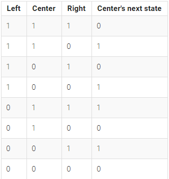
(“规则 90”的名称来自阅读“下一个状态”列:01011010 是十进制的 90。)
在此电路中,创建一个 512 单元系统 ( q[511:0] ),并在每个时钟周期前进一个时间步长。加载输入指示系统的状态应加载data[511:0]。假设边界(q[-1]和q[512])都为零(关闭)。
对于 q[511:0] = 1 的初始状态,前几次迭代是:
1 10 101 1000 10100 100010 101010110000000
这形成了谢尔宾斯基三角形的一半。
module top_module( input clk, input load, input [511:0] data, output [511:0] q ); always @(posedge clk) begin if(load)begin q <= data; end else begin q <= {1'b0,q[511:1]}^{q[510:0],1'b0}; end endendmodule2.2.4.2 Rule 110
规则 110是一个具有有趣特性(例如图灵完备)的一维元胞自动机。
有一个一维的单元格数组(开或关)。在每个时间步,每个单元格的状态都会发生变化。在规则 110 中,每个单元格的下一个状态仅取决于它自己和它的两个邻居,如下表所示:
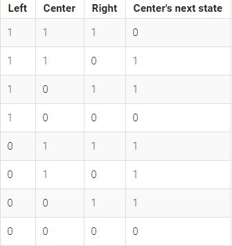
(“规则 110”的名称来自阅读“下一个状态”列:01101110 是十进制的 110。)
在此电路中,创建一个 512 单元系统 ( q[511:0] ),并在每个时钟周期前进一个时间步长。加载输入指示系统的状态应加载data[511:0]。假设边界(q[-1]和q[512])都为零(关闭)。
对于 q[511:0] = 1 的初始状态,前几次迭代是:
1 11 111 1101 11111 110001 111001111010111
module top_module( input clk, input load, input [511:0] data, output [511:0] q); always @(posedge clk)begin if(load)begin q <= data; end else begin q <= (~{1'b0,q[511:1]} & q) | (q & ~{q[510:0],1'b0}) | {~{1'b0,q[511:1]} & {q[510:0],1'b0}} | {~q & {q[510:0],1'b0}}; end endendmodule2.2.4.3 Conway's game of life 16*16
康威的生命游戏是一个二维元胞自动机。
“游戏”是在一个二维单元格上进行的,其中每个单元格要么是 1(活着),要么是 0(死去)。在每个时间步,每个单元格都会根据它拥有的邻居数量来改变状态:
0-1 邻居:单元格变为 0。2个邻居:小区状态不变。3 个邻居:单元格变为 1。4 个以上的邻居:单元格变为 0。该游戏是为无限网格制定的。在这个电路中,我们将使用 16x16 网格。为了让事情更有趣,我们将使用一个 16x16 的环形,其中边环绕到网格的另一边。例如,角单元 (0,0) 有 8 个邻居:(15,1) , (15,0) , (15,15) , (0,1) , (0,15) , (1,1)、(1,0)和(1,15)。16x16 的网格由一个长度为 256 的向量表示,其中每行 16 个单元格由一个子向量表示:q[15:0] 为第 0 行,q[31:16] 为第 1 行,以此类推(此工具接受 SystemVerilog,因此您可以根据需要使用 2D 向量。)
load:在下一个时钟沿将数据加载到q中,用于加载初始状态。q:游戏的 16x16 当前状态,每个时钟周期更新。游戏状态应该在每个时钟周期前进一个时间步长。
约翰·康威,数学家和生命游戏元胞自动机的创造者,于 2020 年 4 月 11 日因 COVID-19 去世。
一个易于理解并测试一些边界条件的测试用例是blinker 256'h7。它是第 0 行第 0-2 列中的 3 个单元格。它在一行 3 个单元格和一列 3 个单元格之间振荡(在第 1 列,第 15、0 和 1 行)。
| 0 | 1 | 1 | |||||||||||||
| 1 | 1 | 1 | |||||||||||||
| 1 | 1 | 1 |
module top_module( input clk, input load, input [255:0] data, output [255:0] q ); reg [3:0] count; integer i; always @(posedge clk) begin if(load)begin q <= data; end else begin for(i=0;i<256;i++)begin if(i == 0)begin count = q[255] + q[240] + q[241] + q[15] + q[1] + q[31] + q[16] + q[17]; end else if(i == 15)begin count = q[254] + q[255] + q[240] + q[14] + q[0] + q[30] + q[31] + q[16]; end else if(i == 240)begin count = q[239] + q[224] + q[225] + q[255] + q[241] + q[15] + q[0] + q[1]; end else if(i == 255)begin count = q[238] + q[239] + q[224] + q[254] + q[240] + q[15] + q[0] + q[14]; end else if( i>0 && i<15)begin count = q[239+i]+q[240+i]+q[241+i]+q[i-1]+q[i+1]+q[i+15]+q[i+16]+q[i+17]; end else if(i>240 && i<255)begin count = q[i-17]+q[i-16]+q[i-15]+q[i-1]+q[i+1]+q[i-239]+q[i-240]+q[i-241]; end else if( i%16 == 0)begin count = q[i-1]+q[i-16]+q[i-15]+q[i+15]+q[i+1]+q[i+31]+q[i+16]+q[i+17]; end else if(i % 16 == 15)begin count = q[i-17]+q[i-16]+q[i-31]+q[i-1]+q[i-15]+q[i+15]+q[i+16]+q[i+1]; end else begin count = q[i-17]+q[i-16]+q[i-15]+q[i-1]+q[i+1]+q[i+15]+q[i+16]+q[i+17]; end case(count) 4'd2:q[i] <= q[i]; 4'd3:q[i] <= 1'b1; default:q[i] <= 1'b0; endcase end end endendmodule2.2.5 Finite State Machines
2.2.5.1 Simple FSM 1 (asynchronous reset)
这是一个具有两种状态的摩尔状态机,一种输入和一种输出。实现这个状态机。请注意,重置状态为 B。
本练习与fsm1相同,但使用异步复位。
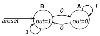
除了编写 FSM 之外,还有其他方法可以做到这一点。但这不是这个练习的重点。
这是一个 TFF 输入反转的 TFF。module top_module( input clk, input areset, // Asynchronous reset to state B input in, output out);// parameter A=0, B=1; reg state, next_state; always @(*) begin // This is a combinational always block case(state) A:begin if(in == 1'b1) next_state <= A; else next_state <= B; end B:begin if(in == 1'b1) next_state <= B; else next_state <= A; end endcase end always @(posedge clk, posedge areset) begin // This is a sequential always block if(areset) state <= B; else state <= next_state; end assign out = (state == B);endmodule两段式状态机:最后使用组合逻辑对结果进行判断,但组合逻辑容易产生毛刺等不稳定因素。
2.2.5.2 Simple FSM 1 (synchronous reset)
这是一个具有两种状态的摩尔状态机,一种输入和一种输出。实现这个状态机。请注意,重置状态为 B。
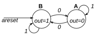
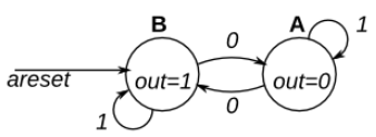
本练习与fsm1相同,但使用同步复位。
module top_module(clk, reset, in, out); input clk; input reset; // Synchronous reset to state B input in; output out;// reg out; parameter A = 0, B = 1; reg present_state, next_state; always @(posedge clk) begin if (reset) begin present_state <= B; end else present_state <= next_state; end always @(*) begin case(present_state) A:begin if(in == 1'b1) next_state = A; else next_state = B; end B:begin if(in == 1'b1) next_state = B; else next_state = A; end endcase end always @(*) begin if(present_state == B) out = 1'b1; else out = 1'b0; endendmodule三段式状态机:采用寄存器输出,可以避免毛刺,改善时序条件,但是三段式状态机分割了两部分组合逻辑(状态转移条件组合逻辑和输出组合逻辑),因此这条路径的时序相对紧张。
2.2.5.3 Simple FSM 2 (asynchronous reset)
这是一个具有两个状态、两个输入和一个输出的摩尔状态机。实现这个状态机。使用异步复位。
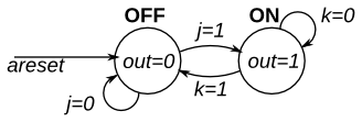
这是一个 JK 触发器。
module top_module( input clk, input areset, // Asynchronous reset to OFF input j, input k, output out); // parameter OFF=0, ON=1; reg state, next_state; always @(*) begin case(state) OFF:begin if(j == 1'b1) next_state = ON; else next_state = OFF; end ON:begin if(k == 1'b1) next_state = OFF; else next_state = ON; end endcase end always @(posedge clk, posedge areset) begin if(areset) state <= OFF; else state <= next_state; end assign out = (state == ON);endmodule2.2.5.4 Simple FSM 2 (synchronous reset)
这是一个具有两个状态、两个输入和一个输出的摩尔状态机。实现这个状态机。
本练习与fsm2相同,但使用同步复位。
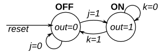
module top_module( input clk, input reset, // Synchronous reset to OFF input j, input k, output out); // parameter OFF=0, ON=1; reg state, next_state; always @(*) begin case(state) OFF:begin if(j == 1'b1) next_state = ON; else next_state = OFF; end ON:begin if(k == 1'b1) next_state = OFF; else next_state = ON; end endcase end always @(posedge clk) begin if(reset) state <= OFF; else state <= next_state; end assign out = (state == ON);endmodule2.2.5.5 Simple state transitions 3
下面是一输入一输出四状态的摩尔状态机的状态转移表。使用以下状态编码:A=2'b00, B=2'b01, C=2'b10, D=2'b11。
仅实现此状态机的状态转换逻辑和输出逻辑(组合逻辑部分)。给定当前状态 ( state),根据状态转换表 计算next_state和输出 (out )。
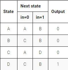
module top_module( input in, input [1:0] state, output [1:0] next_state, output out); parameter A=0, B=1, C=2, D=3; always @(*) begin case(state) A:begin if(in) next_state = B; else next_state = A; end B:begin if(in) next_state = B; else next_state = C; end C:begin if(in) next_state = D; else next_state = A; end D:begin if(in) next_state = B; else next_state = C; end endcase end always @(*) begin if(state == D) out = 1'b1; else out = 1'b0; endendmodule2.2.5.6 Simple one-hot state transitions 3
下面是一输入一输出四状态的摩尔状态机的状态转移表。使用以下单热状态编码:A=4'b0001, B=4'b0010, C=4'b0100, D=4'b1000。
假设 one-hot 编码,通过检查导出状态转换和输出逻辑方程。仅实现此状态机的状态转换逻辑和输出逻辑(组合逻辑部分)。(测试台将使用非一个热输入进行测试,以确保您不会尝试做更复杂的事情)。
单热状态转换逻辑的逻辑方程可以通过查看状态转换图的边缘来导出。
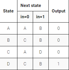
module top_module( input in, input [3:0] state, output [3:0] next_state, output out); parameter A=0, B=1, C=2, D=3; assign next_state[A] = (state[A]&~in)|(state[C]&~in); assign next_state[B] = (state[A]&in)|(state[B]&in)|(state[D]&in); assign next_state[C] = (state[B]&~in)|(state[D]&~in); assign next_state[D] = (state[C]&in); assign out = (state[D]);endmodule用one-hot(独热码)的编码逻辑完成。一般的状态机编码为了方便都是设置为二进制码,但是如果是状态转移是按顺序转移的话,可以使用格雷码,只变化一位,节约功耗。要速度快,可以使用one-hot编码,每次仅需判断一位,当然更消耗更多的寄存器资源,更少的组合逻辑资源。
2.2.5.7 Simple FSM 3 (asynchronous reset)
下面是一输入一输出四状态的摩尔状态机的状态转移表。实现这个状态机。包括将 FSM 重置为状态 A 的异步重置。
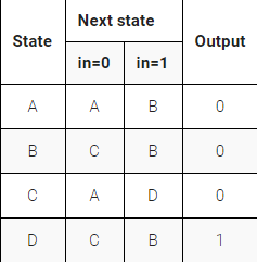
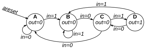
module top_module( input clk, input in, input areset, output out); parameter A=2'b00,B=2'b01,C=2'b10,D=2'b11; reg [1:0] state,next_state; always @(posedge clk,posedge areset) begin if(areset) state <= A; else state <= next_state; end always @(*) begin case(state) A:begin if(in) next_state <= B; else next_state <= A; end B:begin if(in) next_state <= B; else next_state <= C; end C:begin if(in) next_state <= D; else next_state <= A; end D:begin if(in) next_state <= B; else next_state <= C; end endcase end assign out = (state == D);endmodule2.2.5.8 Simple FSM 3 (synchronous reset)
以下是一输入一输出四状态的摩尔状态机的状态转移表。实现这个状态机。包括将 FSM 重置为状态 A 的同步重置。(这与Fsm3的问题相同,但有同步重置。)

module top_module( input clk, input in, input reset, output out); parameter A=2'b00,B=2'b01,C=2'b10,D=2'b11; reg [1:0] state,next_state; always @(posedge clk) begin if(reset) state <= A; else state <= next_state; end always @(*) begin case(state) A:begin if(in) next_state <= B; else next_state <= A; end B:begin if(in) next_state <= B; else next_state <= C; end C:begin if(in) next_state <= D; else next_state <= A; end D:begin if(in) next_state <= B; else next_state <= C; end endcase end assign out = (state == D);endmodule2.2.5.9 Design a more FSM
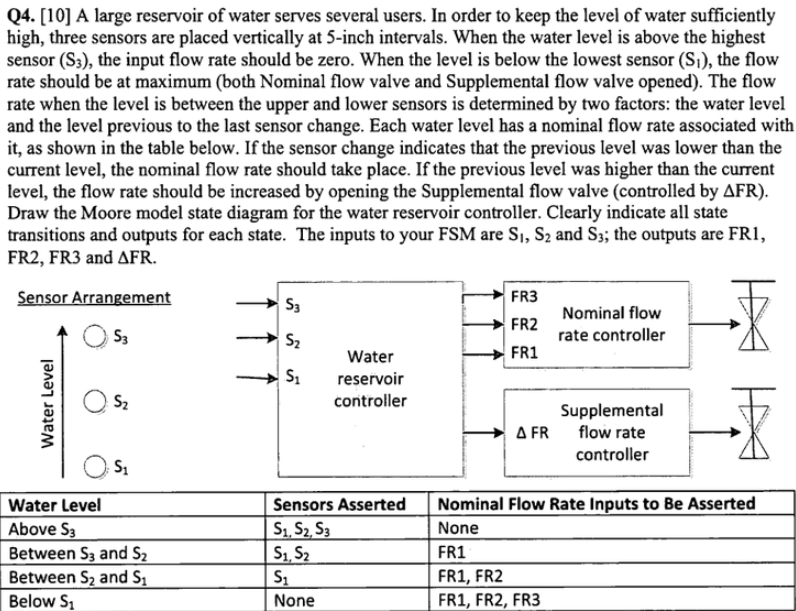
还包括一个高电平有效同步复位,它将状态机复位到相当于水位长时间处于低位的状态(没有传感器断言,并且所有四个输出都断言)。
module top_module ( input clk, input reset, input [3:1] s, output fr3, output fr2, output fr1, output dfr); parameter A=0,B=1,C=2,D=3,E=4,F=5; reg [2:0] state,next_state; always @(*) begin case(state) A:next_state = s[1]?B:A; B:next_state = s[2]?D:(s[1]?B:A); C:next_state = s[2]?D:(s[1]?C:A); D:next_state = s[3]?F:(s[2]?D:C); E:next_state = s[3]?F:(s[2]?E:C); F:next_state = s[3]?F:E; default:next_state = 'x; endcase end always @(posedge clk) begin if(reset) state <= A; else state <= next_state; end always @(*) begin case(state) A:{fr3,fr2,fr1,dfr} = 4'b1111; B:{fr3,fr2,fr1,dfr} = 4'b0110; C:{fr3,fr2,fr1,dfr} = 4'b0111; D:{fr3,fr2,fr1,dfr} = 4'b0010; E:{fr3,fr2,fr1,dfr} = 4'b0011; F:{fr3,fr2,fr1,dfr} = 4'b0000; default: {fr3,fr2,fr1,dfr} = 'x; endcase endendmodule2.2.5.10 Lemmings 1
Lemmings游戏涉及大脑相当简单的小动物。如此简单,我们将使用有限状态机对其进行建模。
在旅鼠的 2D 世界中,旅鼠可以处于以下两种状态之一:向左行走或向右行走。如果遇到障碍物,它会切换方向。特别是,如果 Lemming 撞到左边,它会向右走。如果它撞到右边,它会向左走。如果它同时在两侧碰撞,它仍然会切换方向。
实现一个具有两个状态、两个输入和一个输出的摩尔状态机来模拟这种行为。


module top_module( input clk, input areset, // Freshly brainwashed Lemmings walk left. input bump_left, input bump_right, output walk_left, output walk_right); parameter LEFT=0, RIGHT=1; reg state, next_state; always @(*) begin case(state) LEFT:begin if(bump_left) next_state = RIGHT; else next_state = LEFT; end RIGHT:begin if(bump_right) next_state = LEFT; else next_state = RIGHT; end endcase end always @(posedge clk, posedge areset) begin if(areset) state <= LEFT; else state <= next_state; end assign walk_left = (state == LEFT); assign walk_right = (state == RIGHT);endmodule2.2.5.11 Lemmings 2
除了左右行走之外,如果地面消失在旅鼠脚下,旅鼠还会摔倒(并且可能会“啊啊!”)。
除了左右走动和碰撞时改变方向外,当ground=0时,旅鼠会摔倒并说“啊啊!”。当地面重新出现 ( ground=1 ) 时,旅鼠将继续沿与坠落前相同的方向行走。跌倒时被撞不影响行走方向,与地面消失(但尚未跌倒)同一个周期被撞,或仍在跌倒时再次出现地面时,也不影响行走方向。
构建一个模拟这种行为的有限状态机。
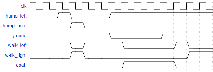
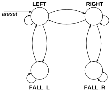
module top_module( input clk, input areset, // Freshly brainwashed Lemmings walk left. input bump_left, input bump_right, input ground, output walk_left, output walk_right, output aaah ); parameter LEFT=2'b00,RIGHT=2'b01,FALL_L=2'b10,FALL_R=2'b11; reg [1:0] state,next_state; always @(*) begin case(state) LEFT:begin if(ground==1'b0) begin next_state = FALL_L; end else if(bump_left) next_state = RIGHT; else next_state = LEFT; end RIGHT:begin if(ground==1'b0) begin next_state = FALL_R; end else if(bump_right) next_state = LEFT; else next_state = RIGHT; end FALL_L:begin if(ground==1'b0) next_state = FALL_L; else next_state = LEFT; end FALL_R:begin if(ground==1'b0) next_state = FALL_R; else next_state = RIGHT; end endcase end always @(posedge clk,posedge areset) begin if(areset) state <= LEFT; else state <= next_state; end assign walk_left = (state == LEFT); assign walk_right = (state == RIGHT); assign aaah = ((state == FALL_L)||(state == FALL_R));endmodule2.2.5.12 Lemmings 3
除了走路和摔倒之外,旅鼠有时会被告知做一些有用的事情,比如挖掘(当dig=1时它开始挖掘)。如果旅鼠当前在地面上行走(ground=1并且没有下落),它可以挖掘,并且会继续挖掘直到它到达另一边(ground=0)。到那时,由于没有地面,它会掉下来(啊啊!),然后一旦再次撞到地面,就继续沿原来的方向行走。与坠落一样,挖掘时被撞到没有效果,并且在坠落或没有地面时被告知要挖掘被忽略。
(换句话说,一只行走的旅鼠可以跌倒、挖掘或切换方向。如果满足这些条件中的一个以上,则跌倒的优先级高于挖掘,挖掘的优先级高于切换方向。)
扩展您的有限状态机来模拟这种行为。
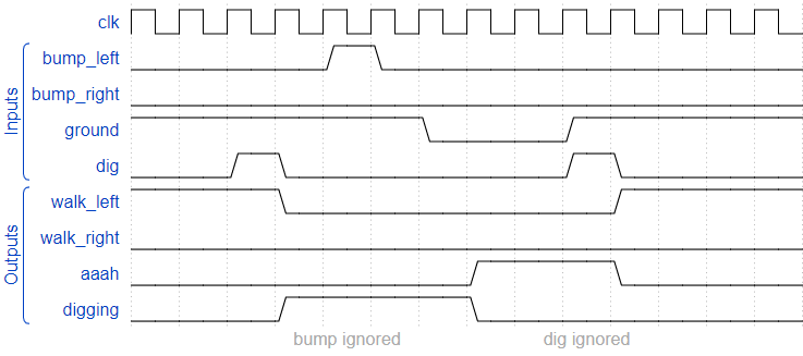
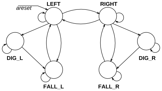
module top_module( input clk, input areset, // Freshly brainwashed Lemmings walk left. input bump_left, input bump_right, input ground, input dig, output walk_left, output walk_right, output aaah, output digging ); parameter LEFT=3'b000,RIGHT=3'b001,DIG_L=3'b010,DIG_R=3'b011,FALL_L=3'b100,FALL_R=3'b101; reg [2:0] state,next_state; always @(*) begin case(state) LEFT:begin if(!ground) next_state = FALL_L; else if(dig) next_state = DIG_L; else if(bump_left) next_state = RIGHT; else next_state = LEFT; end RIGHT:begin if(!ground) next_state = FALL_R; else if(dig) next_state = DIG_R; else if(bump_right) next_state = LEFT; else next_state = RIGHT; end DIG_L:begin if(!ground) next_state = FALL_L; else next_state = DIG_L; end DIG_R:begin if(!ground) next_state = FALL_R; else next_state = DIG_R; end FALL_L:begin if(!ground) next_state = FALL_L; else next_state = LEFT; end FALL_R:begin if(!ground) next_state = FALL_R; else next_state = RIGHT; end endcase end always @(posedge clk,posedge areset) begin if(areset) state <= LEFT; else state <= next_state; end assign walk_left = (state == LEFT); assign walk_right = (state == RIGHT); assign aaah = ((state == FALL_L)||(state == FALL_R)); assign digging = ((state == DIG_L)||(state == DIG_R));endmodule2.2.5.13 Lemmings 4
虽然旅鼠可以行走、跌倒和挖掘,但旅鼠并非无懈可击。如果旅鼠跌落太久然后撞到地面,它可能会飞溅。特别是,如果 Lemming 跌落超过 20 个时钟周期然后撞到地面,它会飞溅并停止行走、跌落或挖掘(所有 4 个输出变为 0),永远(或直到 FSM 重置)。旅鼠在落地前可以坠落的距离没有上限。旅鼠只有在落地时才会飞溅;它们不会在半空中飞溅。
扩展您的有限状态机来模拟这种行为。
跌倒20个周期是可以生存的:

跌倒 21 个周期会导致飞溅:

使用 FSM 控制跟踪旅鼠下落时间的计数器。
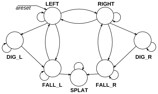
module top_module( input clk, input areset, // Freshly brainwashed Lemmings walk left. input bump_left, input bump_right, input ground, input dig, output walk_left, output walk_right, output aaah, output digging ); parameter LEFT=3'b000,RIGHT=3'b001,DIG_L=3'b010,DIG_R=3'b011,FALL_L=3'b100,FALL_R=3'b101,SPLAT=3'b110,DEAD=3'b111; reg [2:0] state,next_state; reg [4:0] count; initial count = 5'b1; always @(posedge clk,posedge areset) begin if(areset) count <= 5'b1; else if((next_state == FALL_L)||(next_state == FALL_R)) count <= count + 1'b1; else count <= 5'd1; end always @(*) begin case(state) LEFT:begin if(!ground) next_state = FALL_L; else if(dig) next_state = DIG_L; else if(bump_left) next_state = RIGHT; else next_state = LEFT; end RIGHT:begin if(!ground) next_state = FALL_R; else if(dig) next_state = DIG_R; else if(bump_right) next_state = LEFT; else next_state = RIGHT; end DIG_L:begin if(!ground) next_state = FALL_L; else next_state = DIG_L; end DIG_R:begin if(!ground) next_state = FALL_R; else next_state = DIG_R; end FALL_L:begin if((!ground)&&(count<=5'd20)) next_state = FALL_L; else if((!ground)&&(count>5'd20)) next_state = SPLAT; else next_state = LEFT; end FALL_R:begin if((!ground)&&(count<=5'd20)) next_state = FALL_R; else if((!ground)&&(count>5'd20)) next_state = SPLAT; else next_state = RIGHT; end SPLAT:begin if(ground) next_state = DEAD; else next_state = SPLAT; end DEAD:begin next_state = DEAD; end endcase end always @(posedge clk,posedge areset) begin if(areset) state <= LEFT; else state <= next_state; end assign walk_left = (state == LEFT); assign walk_right = (state == RIGHT); assign aaah = ((state == FALL_L)||(state == FALL_R)||(state == SPLAT)); assign digging = ((state == DIG_L)||(state == DIG_R));endmodule2.2.5.14 one-hot FSM
给定以下具有 1 个输入和 2 个输出的状态机:

假设此状态机使用 one-hot 编码,其中state[0]到state[9]分别对应于状态 S0 到 S9。除非另有说明,否则输出为零。
实现状态机的状态转换逻辑和输出逻辑部分(但不是状态触发器)。您在state[9:0]中获得当前状态,并且必须生成next_state[9:0]和两个输出。假设 one-hot 编码,通过检查推导逻辑方程。(测试台将使用非一个热输入进行测试,以确保您不会尝试做更复杂的事情)。
单热状态转换逻辑的逻辑方程可以通过查看状态转换图的边缘来导出。
module top_module( input in, input [9:0] state, output [9:0] next_state, output out1, output out2); parameter s0=4'd0,s1=4'd1,s2=4'd2,s3=4'd3,s4=4'd4,s5=4'd5,s6=4'd6,s7=4'd7,s8=4'd8,s9=4'd9; assign next_state[s0] = ~in&(state[s0]|state[s1]|state[s2]|state[s3]|state[s4]|state[s7]|state[s8]|state[s9]); assign next_state[s1] = in&(state[s0]|state[s8]|state[s9]); assign next_state[s2] = in&(state[s1]); assign next_state[s3] = in&(state[s2]); assign next_state[s4] = in&(state[s3]); assign next_state[s5] = in&(state[s4]); assign next_state[s6] = in&(state[s5]); assign next_state[s7] = in&(state[s6]|state[s7]); assign next_state[s8] = ~in&(state[s5]); assign next_state[s9] = ~in&(state[s6]); assign out1 = state[s8]|state[s9]; assign out2 = state[s7]|state[s9];endmodule2.2.5.15 PS/2 packet parser
PS/2 鼠标协议发送三个字节长的消息。然而,在连续的字节流中,消息的开始和结束位置并不明显。唯一的指示是每个三字节消息的第一个字节总是有bit[3]=1(但其他两个字节的bit[3]可能是1或0,具体取决于数据)。
我们想要一个有限状态机,当给定输入字节流时,它将搜索消息边界。我们将使用的算法是丢弃字节,直到我们看到一个带有bit[3]=1的字节。然后我们假设这是消息的第 1 个字节,并在收到所有 3 个字节后发出消息的接收信号(完成)。
FSM 应该在成功接收到每个消息的第三个字节后立即在循环中 发出完成信号。
一些时序图来解释所需的行为
在无错误的情况下,每三个字节形成一条消息:

发生错误时,搜索字节 1:

请注意,这与1xx序列识别器不同。此处不允许重叠序列:

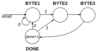
module top_module( input clk, input [7:0] in, input reset, // Synchronous reset output done); parameter BYTE1=2'b00,BYTE2=2'b01,BYTE3=2'b10,DONE=2'b11; reg [1:0] state,next_state; always @(*) begin case(state) BYTE1:begin if(in[3]) next_state = BYTE2; else next_state = BYTE1; end BYTE2:next_state = BYTE3; BYTE3:next_state = DONE; DONE:begin if(in[3]) next_state = BYTE2; else next_state = BYTE1; end endcase end always @(posedge clk) begin if(reset) state <= BYTE1; else state <= next_state; end assign done = (state == DONE);endmodule2.2.5.13 PS/2 packet parser and datapath
现在您有了一个状态机,可以识别 PS/2 字节流中的三字节消息,添加一个数据路径,该路径也将在收到数据包时输出 24 位(3 字节)消息(out_bytes[23:16]是第一个字节,out_bytes[15:8]是第二个字节,依此类推)。
每当断言完成信号时, out_bytes 都需要有效。您可以在其他时间输出任何内容(即,不关心)。例如:
使用PS/2 packet parser中的 FSM并添加数据路径以捕获传入字节。
module top_module( input clk, input [7:0] in, input reset, // Synchronous reset output [23:0] out_bytes, output done); parameter BYTE1=2'b00,BYTE2=2'b01,BYTE3=2'b10,DONE=2'b11; reg [1:0] state,next_state; always @(*) begin case(state) BYTE1:begin if(in[3]) next_state = BYTE2; else next_state = BYTE1; end BYTE2:next_state = BYTE3; BYTE3:next_state = DONE; DONE:begin if(in[3]) next_state = BYTE2; else next_state = BYTE1; end endcase end always @(posedge clk) begin if(reset) state <= BYTE1; else state <= next_state; end assign done = (state == DONE); always @(posedge clk) begin if((state==BYTE1)&&(next_state==BYTE2)||(state==DONE)&&(next_state==BYTE2)) begin out_bytes[23:16] <= in; end else if((state==BYTE2)&&(next_state==BYTE3)) begin out_bytes[15:8] <= in; end else if((state==BYTE3)&&(next_state==DONE)) out_bytes[7:0] <= in; endendmodule2.2.5.14 Serial receiver
在许多(较旧的)串行通信协议中,每个数据字节都与一个起始位和一个停止位一起发送,以帮助接收器从位流中划定字节。一种常见的方案是使用 1 个起始位 (0)、8 个数据位和 1 个停止位 (1)。当没有传输任何内容(空闲)时,该线路也处于逻辑 1。
设计一个有限状态机,当给定比特流时,它将识别何时正确接收到字节。它需要识别起始位,等待所有 8 个数据位,然后验证停止位是否正确。如果停止位未按预期出现,则 FSM 必须等到找到停止位后再尝试接收下一个字节。
一些时序图
无错误:

未找到停止位。第一个字节被丢弃:

module top_module( input clk, input in, input reset, // Synchronous reset output done); parameter start=4'd0,D1=4'd1,D2=4'd2,D3=4'd3,D4=4'd4,D5=4'd5,D6=4'd6,D7=4'd7,D8=4'd8,stop=4'd9,idle=4'd10,WAIT=4'd11; reg [3:0] state,next_state; always @(*) begin case(state) start:next_state = D1; D1:next_state = D2; D2:next_state = D3; D3:next_state = D4; D4:next_state = D5; D5:next_state = D6; D6:next_state = D7; D7:next_state = D8; D8:begin if(in) next_state = stop; else next_state = WAIT; end stop:begin if(in) next_state = idle; else next_state = start; end idle:begin if(in) next_state = idle; else next_state = start; end WAIT:begin if(in) next_state = idle; else next_state = WAIT; end default:next_state = idle; endcase end always @(posedge clk) begin if(reset) state <= idle; else state <= next_state; end assign done = (state == stop);endmodule2.2.5.15 Serial receiver and datapath
现在您有了一个有限状态机,可以识别何时在串行比特流中正确接收到字节,添加一个数据路径来输出正确接收到的数据字节。out_byte需要在done为1时有效,否则不在乎。
请注意,串行协议首先发送最低有效位。
一些时序图
无错误:

串行比特流需要一次移一位,然后并行读出。
module top_module( input clk, input in, input reset, // Synchronous reset output [7:0] out_byte, output done); integer i; parameter start=4'd0,D1=4'd1,D2=4'd2,D3=4'd3,D4=4'd4,D5=4'd5,D6=4'd6,D7=4'd7,D8=4'd8,stop=4'd9,idle=4'd10,WAIT=4'd11; reg [3:0] state,next_state; reg [7:0] temp_in; always @(*) begin case(state) start: begin next_state = D1; temp_in[0] = in; end D1: begin next_state = D2; temp_in[1] = in; end D2: begin next_state = D3; temp_in[2] = in; end D3: begin next_state = D4; temp_in[3] = in; end D4: begin next_state = D5; temp_in[4] = in; end D5: begin next_state = D6; temp_in[5] = in; end D6: begin next_state = D7; temp_in[6] = in; end D7: begin next_state = D8; temp_in[7] = in; end D8:begin if(in) next_state = stop; else next_state = WAIT; end stop:begin if(in) next_state = idle; else next_state = start; end idle:begin if(in) next_state = idle; else next_state = start; end WAIT:begin if(in) next_state = idle; else next_state = WAIT; end default:next_state = idle; endcase end always @(posedge clk) begin if(reset) state <= idle; else state <= next_state; end assign done = (state == stop); assign out_byte = done?temp_in:8'b0;endmodule2.2.5.16 Serial receiver with pariting checking
我们想为串行接收器添加奇偶校验。奇偶校验在每个数据字节后增加一位。我们将使用奇校验,其中接收到的 9 位中1的数量必须是奇数。例如,101001011满足奇校验(有 5 个1 s),但001001011不满足。
更改您的 FSM 和数据路径以执行奇校验检查。只有当一个字节被正确接收并且它的奇偶校验通过时,才断言完成信号。像串行接收器FSM,这个 FSM 需要识别起始位,等待所有 9 个(数据和奇偶校验)位,然后验证停止位是否正确。如果停止位未按预期出现,则 FSM 必须等到找到停止位后再尝试接收下一个字节。
为您提供了以下模块,可用于计算输入流的奇偶校验(这是一个带复位的 TFF)。预期用途是应该给它输入比特流,并在适当的时间重置,以便计算每个字节 中1的比特数。
module parity ( input clk, input reset, input in, output reg odd); always @(posedge clk) if (reset) odd <= 0; else if (in) odd <= ~odd;endmodule
请注意,串行协议先发送最低有效位,然后再发送 8 个数据位之后的奇偶校验位。
一些时序图
没有构图错误。第一个字节奇校验通过,第二个字节失败。

module top_module( input clk, input in, input reset, // Synchronous reset output [7:0] out_byte, output done); parameter idle = 3'd0,start = 3'd1,data = 3'd2,Parity = 3'd3,stop = 3'd4,WAIT = 3'd5; reg [2:0] state,next_state; reg [3:0] counter; reg [7:0] temp_in; wire odd; wire en; always @(posedge clk) begin if(reset) state <= idle; else state <= next_state; end always @(*) begin case(state) idle:begin if(in) next_state = idle; else next_state = start; end start:next_state = data; data:begin if(counter == 4'd8) next_state = Parity; else next_state = data; end Parity:begin if(in) next_state = stop; else next_state = WAIT; end stop:begin if(in) next_state = idle; else next_state = start; end WAIT:begin if(in) next_state = idle; else next_state = WAIT; end endcase end always @(posedge clk) begin if(reset) begin done <= 1'b0; out_byte <= 8'd0; counter <= 4'd0; end else begin case(next_state) idle:begin done <= 1'b0; out_byte <= 8'd0; counter <= 4'd0; end start:begin done <= 1'b0; out_byte <= 8'd0; counter <= 4'd0; end data:begin counter <= counter + 1'b1; done <= 1'b0; temp_in[counter] <= in; out_byte <= 8'd0; end Parity:begin done <= 1'b0; out_byte <= 8'd0; counter <= 4'd0; end stop:begin if(odd == 1'b1) begin done <= 1'b1; out_byte <= temp_in; end else begin done <= 1'b0; out_byte <= 8'd0; end end WAIT:begin done <= 1'b0; out_byte <= 8'd0; end default:begin done <= 1'b0; out_byte <= 8'd0; counter <= 4'd0; end endcase end end assign en = (reset == 1'b1 || next_state == idle || next_state == start); parity u1 (.clk(clk),.reset(en),.in(in),.odd(odd)); endmodule2.2.5.17 Sequence recognition
同步HDLC成帧涉及对数据的连续比特流进行解码,以寻找指示帧(数据包)开始和结束的比特模式。恰好看到 6 个连续的 1(即01111110)是指示帧边界的“标志”。为避免数据流意外包含“标志”,发送方在每 5 个连续的 1 后插入一个零,接收方必须检测并丢弃该 0。如果有 7 个或更多连续的 1,我们还需要发出错误信号。
创建一个有限状态机来识别这三个序列:
0111110 : 需要丢弃信号位(光盘)。01111110:标记帧的开始/结束(标志)。01111111...:错误(7 个或更多 1s)(err)。当 FSM 被重置时,它应该处于一个状态,就像之前的输入为 0 一样。
以下是一些说明所需操作的示例序列。
丢弃0111110:

标志01111110:

重置行为和错误01111111...:

实现这个状态机。
使用具有大约 10 个状态的摩尔状态机。

module top_module( input clk, input reset, // Synchronous reset input in, output disc, output flag, output err); parameter NONE = 4'd0,ONE = 4'd1,TWO = 4'd2,THREE = 4'd3,FOUR = 4'd4,FIVE = 4'd5,SIX = 4'd6,ERROR = 4'd7,FLAG = 4'd8,DISCARD = 4'd9; reg [3:0] state,next_state; always @(posedge clk) begin if(reset) state <= NONE; else state <= next_state; end always @(*) begin case(state) NONE:next_state = in?ONE:NONE; ONE:next_state = in?TWO:NONE; TWO:next_state = in?THREE:NONE; THREE:next_state = in?FOUR:NONE; FOUR:next_state = in?FIVE:NONE; FIVE:next_state = in?SIX:DISCARD; SIX:next_state = in?ERROR:FLAG; ERROR:next_state = in?ERROR:NONE; FLAG:next_state = in?ONE:NONE; DISCARD:next_state = in?ONE:NONE; endcase end assign err = (state == ERROR); assign flag = (state == FLAG); assign disc = (state == DISCARD);endmodule2.2.5.18 Design a Mealy FSM
实现一个Mealy类型的有限状态机,它可以识别名为x的输入信号上的序列“101” 。您的 FSM 应该有一个输出信号z,当检测到“101”序列时,它被断言为逻辑 1。您的 FSM 还应该有一个低电平有效的异步复位。您的状态机中可能只有 3 个状态。您的 FSM 应该能够识别重叠序列。
module top_module ( input clk, input aresetn, // Asynchronous active-low reset input x, output z ); parameter s0 = 2'b00,s1 = 2'b01,s2 = 2'b10; reg [1:0] state,next_state; always @(posedge clk or negedge aresetn) begin if(!aresetn) state <= s0; else state <= next_state; end always @(*) begin case(state) s0:next_state = x?s1:s0; s1:next_state = x?s1:s2; s2:next_state = x?s1:s0; default:next_state = s0; endcase end always @(*) begin case(state) s0:z = 1'b0; s1:z = 1'b0; s2:z = x; endcase endendmodule2.2.5.19 Q5a:Serial two's complementer(Moore FSM)
你要设计一个单输入单输出串行 2 的补码摩尔状态机。输入 (x) 是一系列位(每个时钟周期一个),从数字的最低有效位开始,输出 (Z) 是输入的 2 的补码。机器将接受任意长度的输入数字。该电路需要异步复位。转换在释放复位时开始,在复位时停止。
例如:

module top_module ( input clk, input areset, input x, output z); parameter A=2'd0,B=2'd1,C=2'd2; reg [1:0] state,next_state; always @(posedge clk,posedge areset) begin if(areset) state <= A; else state <= next_state; end always @(*) begin case(state) A:next_state = x?B:A; B:next_state = x?C:B; C:next_state = x?C:B; default:next_state = A; endcase end assign z = (state == B);endmodule2.2.5.20 Q5b:Serial two's complementer(Mealy FSM)
下图是 2 的补码的Mealy机器实现。使用 one-hot 编码实现。
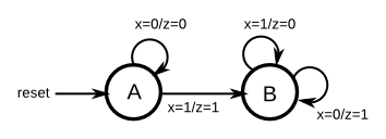

module top_module ( input clk, input areset, input x, output z); parameter A=1'b0,B=1'b1; reg state,next_state; always @(posedge clk,posedge areset) begin if(areset) state <= A; else state <= next_state; end always @(*) begin case(state) A:next_state = x?B:A; B:next_state = B; endcase end always @(*) begin case(state) A:z = x; B:z = ~x; endcase endendmodule2.2.5.21 Q3a:FSM
考虑一个具有输入s和w的有限状态机。假设 FSM 以称为A的复位状态开始,如下所示。只要s = 0, FSM 就保持在状态A ,当s = 1 时,它移动到状态 B。一旦处于状态B,FSM在接下来的三个时钟周期内检查输入w的值。如果w = 1 在恰好两个时钟周期中,则 FSM 必须 在下一个时钟周期中将输出z设置为 1。否则z必须为 0。FSM 继续检查w接下来的三个时钟周期,依此类推。下面的时序图说明了不同w值所需的z值。
使用尽可能少的状态。请注意,s输入仅用于状态A,因此您只需要考虑w输入。

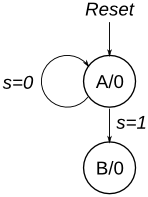
module top_module ( input clk, input reset, // Synchronous reset input s, input w, output z); parameter A=1'b0,B=1'b1; reg state,next_state; always @(posedge clk) begin if(reset) state <= A; else state <= next_state; end always @(*) begin case(state) A:next_state = s?B:A; B:next_state = B; endcase end reg w1,w2; always @(posedge clk) begin if(reset) begin w1 <= 1'b0; w2 <= 1'b0; end else if(next_state == B) begin w1 <= w; w2 <= w1; end else begin w1 <= 1'b0; w2 <= 1'b0; end end always @(posedge clk) begin if(reset) z <= 1'b0; else if((state == B)&&(counter == 2'd0)) begin if(w&w1&~w2 | w&~w1&w2 | ~w&w1&w2) begin z <= 1'b1; end else begin z <= 1'b0; end end else z <= 1'b0; end reg [1:0] counter; always @(posedge clk) begin if(reset) counter <= 2'd0; else if(counter == 2'd2) counter <= 2'd0; else if(next_state == B) counter <= counter + 1'b1; end endmodule2.2.5.22 Q3b FSM
给定如下所示的状态分配表,实现有限状态机。重置应该将 FSM 重置为状态 000。
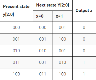
module top_module ( input clk, input reset, // Synchronous reset input x, output z); parameter A = 3'b000,B = 3'b001,C = 3'b010,D = 3'b011,E = 3'b100; reg [2:0] state,next_state; always @(posedge clk) begin if(reset) state <= A; else state <= next_state; end always @(*) begin case(state) A:next_state = x?B:A; B:next_state = x?E:B; C:next_state = x?B:C; D:next_state = x?C:B; E:next_state = x?E:D; endcase end assign z = ((state == D)||(state == E));endmodule2.2.5.23 Q3c:FSM logic
给定如下所示的状态分配表,实现逻辑函数 Y[0] 和 z。
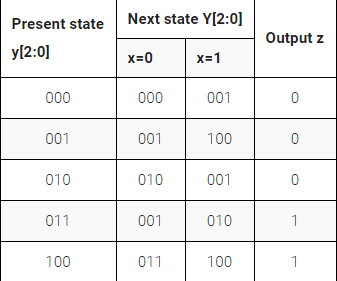
module top_module ( input clk, input [2:0] y, input x, output Y0, output z); parameter A = 3'b000,B = 3'b001,C = 3'b010,D = 3'b011,E = 3'b100; reg [2:0] next_state; always @(*) begin case(y) A:next_state = x?B:A; B:next_state = x?E:B; C:next_state = x?B:C; D:next_state = x?C:B; E:next_state = x?E:D; endcase end assign Y0 = ((next_state == B)||(next_state == D)); assign z = ((y == D)||(y == E));endmodule2.2.5.24 Q6b:FSM next _state logic
考虑如下所示的状态机,它有一个输入w和一个输出z。
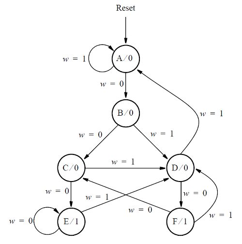
假设您希望使用三个触发器和状态代码y[3:1] = 000, 001, ..., 101 分别用于状态 A、B、...、F 来实现 FSM。显示此 FSM 的状态分配表。导出触发器y[2]的下一个状态表达式。
只为y[2]实现下一个状态逻辑。(这更像是一个 FSM 问题,而不是 Verilog 编码问题。哦,好吧。)
module top_module ( input [3:1] y, input w, output Y2); parameter A = 3'b000,B = 3'b001,C = 3'b010,D = 3'b011,E = 3'b100,F = 3'b101; reg [2:0] next_state; always @(*) begin case(y) A:next_state = w?A:B; B:next_state = w?D:C; C:next_state = w?D:E; D:next_state = w?A:F; E:next_state = w?D:E; F:next_state = w?D:C; endcase end assign Y2 = ((next_state == C)||(next_state == D));endmodule2.2.5.25 Q6c:FSM one-hot next-state log
考虑如下所示的状态机,它有一个输入w和一个输出z。
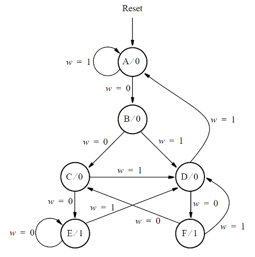
对于这一部分,假设状态分配 'y[6:1] = 000001, 000010, 000100, 001000, 010000, 100000 分别用于状态 A、B、...、F 的 one-hot 代码。
为下一状态信号 Y2 和 Y4 编写逻辑表达式。(通过假设 one-hot 编码的检查推导出逻辑方程。测试台将使用非 one hot 输入进行测试,以确保您不会尝试做更复杂的事情)。
module top_module ( input [6:1] y, input w, output Y2, output Y4); parameter A = 3'd1,B = 3'd2,C = 3'd3,D = 3'd4,E = 3'd5,F = 3'd6; reg [6:0] next_state; always @(*) begin case(y) A:next_state = w?A:B; B:next_state = w?D:C; C:next_state = w?D:E; D:next_state = w?A:F; E:next_state = w?D:E; F:next_state = w?D:C; default:next_state = A; endcase end assign Y2 = ~w&y[A]; assign Y4 = w&(y[B]|y[C]|y[E]|y[F]);endmodule2.2.5.26 Q6:FSM
考虑如下所示的状态机,它有一个输入w和一个输出z。
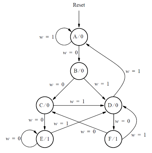
实现状态机。(这部分不在期中,但编写 FSM 是一种很好的做法)。
module top_module ( input clk, input reset, // synchronous reset input w, output z); parameter A = 3'b000,B = 3'b001,C = 3'b010,D = 3'b011,E = 3'b100,F = 3'b101; reg [2:0] state,next_state; always @(posedge clk) begin if(reset) state <= A; else state <= next_state; end always @(*) begin case(state) A:next_state = w?A:B; B:next_state = w?D:C; C:next_state = w?D:E; D:next_state = w?A:F; E:next_state = w?D:E; F:next_state = w?D:C; endcase end assign z = ((state == E)||(state == F));endmodule2.2.5.27 Q2a:FSM
考虑如下所示的状态图。
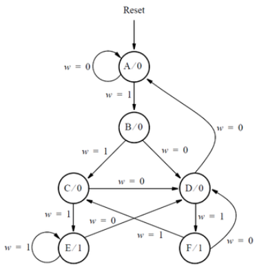
编写代表此 FSM 的完整 Verilog 代码。就像在讲座中所做的那样,对状态表和状态触发器使用单独的always块。使用连续赋值语句或always块(由您自行决定)描述 FSM 输出,称为z 。分配您希望使用的任何州代码。
module top_module ( input clk, input reset, // Synchronous active-high reset input w, output z); parameter A = 3'b000,B = 3'b001,C = 3'b010,D = 3'b011,E = 3'b100,F = 3'b101; reg [2:0] state,next_state; always @(posedge clk) begin if(reset) state <= A; else state <= next_state; end always @(*) begin case(state) A:next_state = w?B:A; B:next_state = w?C:D; C:next_state = w?E:D; D:next_state = w?F:A; E:next_state = w?E:D; F:next_state = w?C:D; endcase end assign z = ((state == E)||(state == F));endmodule2.2.5.28 Q2b:One-hot FSM equations
这个问题的状态图再次显示在下面。
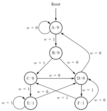
假设在状态分配y[5:0] = 000001(A), 000010(B), 000100(C), 001000(D), 010000(E), 100000(F) 中使用 one-hot 代码
为信号Y1写一个逻辑表达式,它是状态触发器y[1]的输入。
为信号Y3写一个逻辑表达式,它是状态触发器y[3]的输入。
(通过假设 one-hot 编码的检查推导出逻辑方程。测试台将使用非 one hot 输入进行测试,以确保您不会尝试做更复杂的事情)。
单热状态转换逻辑的逻辑方程可以通过查看状态转换图的边缘来导出。
module top_module ( input [5:0] y, input w, output Y1, output Y3); parameter A = 3'b000,B = 3'b001,C = 3'b010,D = 3'b011,E = 3'b100,F = 3'b101; assign Y1 = w&y[A]; assign Y3 = ~w&(y[B]|y[C]|y[E]|y[F]);endmodule2.2.5.29 Q2a:FSM
考虑下图所示状态图描述的 FSM:
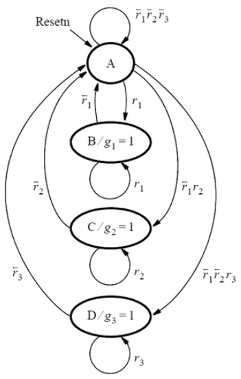
该 FSM 充当仲裁电路,控制三个请求设备对某种类型资源的访问。每个设备通过设置信号r[i] = 1 来请求资源,其中r[i]是r[1]、r[2]或r[3]。每个 r[i] 是 FSM 的输入信号,代表三个设备之一。只要没有请求,FSM 就会保持在状态A。当一个或多个请求发生时,FSM 决定哪个设备接收到使用资源的授权,并更改为将该设备的g[i]信号设置为 1 的状态。每个g[i]是 FSM 的输出。有一个优先级系统,设备 1 的优先级高于设备 2,设备 3 的优先级最低。因此,例如,如果设备 3 是在 FSM 处于状态A时发出请求的唯一设备,则设备 3 将仅接收授权。一旦设备i被 FSM 授予授权,只要其请求r[i] = 1,该设备就会继续接收授权。
编写代表此 FSM 的完整 Verilog 代码。就像在讲座中所做的那样,对状态表和状态触发器使用单独的 always 块。使用连续赋值语句或 always 块(由您自行决定)描述 FSM 输出g[i] 。
module top_module ( input clk, input resetn, // active-low synchronous reset input [3:1] r, // request output [3:1] g // grant); parameter A = 2'd0,B = 2'd1,C = 2'd2,D = 2'd3; reg [1:0] state,next_state; always @(posedge clk) begin if(!resetn) state <= A; else state <= next_state; end always @(*) begin case(state) A:begin if(r[1]) next_state = B; else if(~r[1]&r[2]) next_state = C; else if(~r[1]&~r[2]&r[3]) next_state = D; else if(~r[1]&~r[2]&~r[3]) next_state = A; end B:begin if(~r[1]) next_state = A; else next_state = B; end C:begin if(~r[2]) next_state = A; else next_state = C; end D:begin if(~r[3]) next_state = A; else next_state = D; end endcase end assign g[1] = (state == B); assign g[2] = (state == C); assign g[3] = (state == D);endmodule2.2.5.30 Q2b:Another FSM
考虑一个用于控制某种电机的有限状态机。FSM 具有 来自电机的输入x和y ,并产生控制电机的输出f和g。还有一个称为clk的时钟输入和一个称为resetn的复位输入。
FSM 必须按如下方式工作。只要复位输入被置位,FSM 就保持在开始状态,称为状态A。当复位信号无效时,在下一个时钟沿之后,FSM 必须将输出f设置为 1 一个时钟周期。然后,FSM 必须监控 x输入。当x在三个连续的时钟周期中产生值 1、0、1 时,应在下一个时钟周期将g设置为 1。在保持g = 1 的同时,FSM 必须监控y 输入。如果y在最多两个时钟周期内为 1,则 FSM 应保持g= 1 永久(即,直到重置)。但如果y在两个时钟周期内未变为 1,则 FSM 应永久设置g = 0(直到复位)。
(最初的考试问题只要求提供状态图。但在这里,实现 FSM。)
FSM 直到f之后的周期为 1才 开始监视x输入。
module top_module ( input clk, input resetn, // active-low synchronous reset input x, input y, output f, output g); parameter FOUT=4'd0,A=4'd1,B=4'd2,C=4'd3,D=4'd4,E=4'd5,FONE=4'd6,FZERO=4'd7,IDEL=4'd8; reg [3:0] state,next_state; always @(posedge clk) begin if(!resetn) state <= IDEL; else state <= next_state; end always @(*) begin case(state) IDEL:next_state = FOUT; FOUT:next_state = A; A:next_state = x?B:A; B:next_state = x?B:C; C:next_state = x?D:A; D:next_state = y?FONE:E; E:next_state = y?FONE:FZERO; FONE:next_state = FONE; FZERO:next_state = FZERO; default : next_state = IDEL; endcase end assign f = (state == FOUT); assign g = ((state == D)||(state == E)||(state == FONE));endmodule2.3 Building Large Circuits
2.3.1 couter with 1000
建立一个从 0 到 999 的计数器,包括 0 到 999,周期为 1000 个周期。复位输入是同步的,应将计数器复位为 0。

module top_module ( input clk, input reset, output [9:0] q); always @(posedge clk) begin if(reset||q>=10'd999) q <= 10'b0; else q <= q + 1'b1; endendmodule2.3.2 4-bit shfit register and down counter
构建一个四位移位寄存器,该寄存器也用作递减计数器。当shift_ena为 1时,数据首先移入最高有效位。当count_ena为 1时,当前在移位寄存器中的数字递减。由于整个系统不会同时使用shift_ena和count_ena,因此您的电路无关紧要如果两个控制输入都为 1(这主要意味着哪种情况获得更高优先级并不重要)。

module top_module ( input clk, input shift_ena, input count_ena, input data, output [3:0] q); always @(posedge clk) begin if(shift_ena) begin q[0] <= data; q[1] <= q[0]; q[2] <= q[1]; q[3] <= q[2]; end else if(count_ena) q <= q - 1'b1; else q <= q; endendmodule2.3.3 FSM:Sequence 1101 recognizer
构建一个有限状态机,在输入比特流中搜索序列 1101。找到序列后,应将start_shifting设置为 1,直到重置。陷入最终状态旨在模拟在尚未实现的更大 FSM 中进入其他状态。我们将在接下来的几个练习中扩展这个 FSM。

module top_module ( input clk, input reset, // Synchronous reset input data, output start_shifting); parameter s0=3'd0,s1=3'd1,s2=3'd2,s3=3'd3,s4=3'd4; reg [2:0] state,next_state; always @(posedge clk) begin if(reset) state <= s0; else state <= next_state; end always @(*) begin case(state) s0:next_state = data?s1:s0; s1:next_state = data?s2:s0; s2:next_state = data?s2:s3; s3:next_state = data?s4:s0; s4:next_state = s4; default:next_state = s0; endcase end always @(posedge clk) begin if(reset) begin start_shifting <= 1'b0; end else if(next_state == s4) begin start_shifting <= 1'b1; end endendmodule2.3.4 FSM:Enable shift register
作为用于控制移位寄存器的 FSM 的一部分,我们希望能够在检测到正确的位模式时启用移位寄存器恰好 4 个时钟周期。SM 的这一部分仅处理启用 4 个周期的移位寄存器。

module top_module ( input clk, input reset, // Synchronous reset output shift_ena); reg [3:0] counter; always @(posedge clk) begin if(reset) counter <= 4'b0; else if(shift_ena) begin if(counter >= 4'd3) counter <= 4'b0; else counter <= counter + 1'b1; end end always @(posedge clk) begin if(reset) shift_ena <= 1'b1; else if((shift_ena == 1'b1)&(counter >= 4'd3)) shift_ena <= 1'b0; endendmodule2.3.5 FSM:The complete FSM
我们想创建一个计时器:
当检测到特定模式 (1101) 时开始,再移 4 位以确定延迟的持续时间,等待计数器完成计数,并且通知用户并等待用户确认计时器。在这个问题中,只实现控制定时器的有限状态机。此处不包括数据路径(计数器和一些比较器)。
串行数据在数据输入引脚上可用。当接收到模式 1101 时,状态机必须断言输出shift_ena正好 4 个时钟周期。
之后,状态机断言其计数输出以指示它正在等待计数器,并一直等到输入done_counting为高。
此时,状态机必须断言完成以通知用户定时器已超时,并等待直到输入ack为 1,然后才被重置以寻找下一次出现的启动序列 (1101)。
状态机应重置为开始搜索输入序列 1101 的状态。
这是预期输入和输出的示例。'x' 状态读起来可能有点混乱。它们表明 FSM 不应该关心该周期中的特定输入信号。例如,一旦检测到 1101 模式,FSM 将不再查看数据输入,直到完成其他所有操作后恢复搜索。 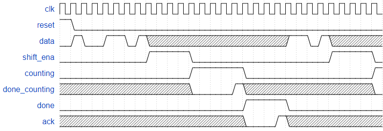

module top_module ( input clk, input reset, // Synchronous reset input data, output shift_ena, output counting, input done_counting, output done, input ack ); parameter s=4'd0,s1=4'd1,s11=4'd2,s110=4'd3,b0=4'd4,b1=4'd5,b2=4'd6,b3=4'd7,count=4'd8,WAIT=4'd9; reg [3:0] state,next_state; always @(posedge clk) begin if(reset) state <= s; else state <= next_state; end always @(*) begin case(state) s:next_state = data?s1:s; s1:next_state = data?s11:s; s11:next_state = data?s11:s110; s110:next_state = data?b0:s; b0:next_state = b1; b1:next_state = b2; b2:next_state = b3; b3:next_state = count; count:next_state = done_counting?WAIT:count; WAIT:next_state = ack?s:WAIT; endcase end assign shift_ena = ((state == b0)||(state == b1)||(state == b2)||(state == b3)); assign counting = (state == count); assign done = (state == WAIT);endmodule2.3.6 The complete timer
我们想创建一个带有一个输入的计时器:
当检测到特定输入模式 (1101) 时启动,再移 4 位以确定延迟的持续时间,等待计数器完成计数,并且通知用户并等待用户确认计时器。串行数据在数据输入引脚上可用。当接收到模式 1101 时,电路必须移入接下来的 4 位,首先是最高有效位。这 4 位决定了定时器延迟的持续时间。我将其称为delay[3:0]。
之后,状态机断言其计数输出以指示它正在计数。状态机必须精确计数(delay[3:0] + 1) * 1000 个时钟周期。例如,delay=0 表示计数 1000 个周期,delay=5 表示计数 6000 个周期。同时输出当前剩余时间。这应该等于delay 1000 个周期,然后delay-1 1000 个周期,依此类推,直到 0 1000 个周期。当电路不计数时,count[3:0] 输出是无关紧要的(任何值方便您实现)。
此时,电路必须断言done以通知用户计时器已超时,并等待输入ack为 1,然后再复位以查找下一次出现的启动序列 (1101)。
电路应重置为开始搜索输入序列 1101 的状态。
这是预期输入和输出的示例。'x' 状态读起来可能有点混乱。它们表明 FSM 不应该关心该周期中的特定输入信号。例如,一旦读取了 1101 和 delay[3:0],电路就不再查看数据输入,直到在其他所有操作完成后恢复搜索。在本例中,电路计数 2000 个时钟周期,因为 delay[3:0] 值为 4'b0001。最后几个周期以 delay[3:0] = 4'b1110 开始另一个计数,它将计数 15000 个周期。

硬件应该是 上面的FSM、移位寄存器+计数器。您可能需要更多的比较器。
如果组件位于它们自己的始终块中,则可以将所有代码放在单个模块中,只要清楚哪个代码块对应于哪个硬件块即可。不要将多个 always 块合并在一起,因为这很难阅读并且容易出错。
module top_module ( input clk, input reset, // Synchronous reset input data, output [3:0] count, output counting, output done, input ack ); parameter s=4'd0,s1=4'd1,s11=4'd2,s110=4'd3,b0=4'd4,b1=4'd5,b2=4'd6,b3=4'd7,Count=4'd8,WAIT=4'd9; reg [3:0] state,next_state; reg [3:0] temp_in; reg [15:0] counter; reg [3:0] a; wire done_counting; always @(posedge clk) begin if(reset) state <= s; else state <= next_state; end always @(posedge clk) begin if(reset) counter <= 16'd0; else if(next_state == WAIT) counter <= 16'd0; else if(next_state == Count) counter <= counter + 1'b1; end always @(*) begin if(counter <= 16'd1000) a = 4'd0; else if(counter <= 16'd2000) a = 4'd1; else if(counter <= 16'd3000) a = 4'd2; else if(counter <= 16'd4000) a = 4'd3; else if(counter <= 16'd5000) a = 4'd4; else if(counter <= 16'd6000) a = 4'd5; else if(counter <= 16'd7000) a = 4'd6; else if(counter <= 16'd8000) a = 4'd7; else if(counter <= 16'd9000) a = 4'd8; else if(counter <= 16'd10000) a = 4'd9; else if(counter <= 16'd11000) a = 4'd10; else if(counter <= 16'd12000) a = 4'd11; else if(counter <= 16'd13000) a = 4'd12; else if(counter <= 16'd14000) a = 4'd13; else if(counter <= 16'd15000) a = 4'd14; else a = 4'd15; end assign done_counting = ((state == Count)&(counter == (temp_in + 1)*1000))?1'b1:1'b0; always @(*) begin case(state) s:next_state = data?s1:s; s1:next_state = data?s11:s; s11:next_state = data?s11:s110; s110:next_state = data?b0:s; b0:begin next_state = b1;temp_in[3] = data; end b1:begin next_state = b2;temp_in[2] = data; end b2:begin next_state = b3;temp_in[1] = data; end b3:begin next_state = Count;temp_in[0] = data; end Count:next_state = done_counting?WAIT:Count; WAIT:next_state = ack?s:WAIT; endcase end assign count = (state == Count)?(temp_in - a):4'd0; assign counting = (state == Count); assign done = (state == WAIT);endmodule2.3.7 FSM:One-hot logic equations
给定以下具有 3 个输入、3 个输出和 10 个状态的状态机:
假设使用以下 one-hot 编码, 通过检查导出下一状态逻辑方程和输出逻辑方程: (S, S1, S11, S110, B0, B1, B2, B3, Count, Wait) = (10'b0000000001, 10 'b0000000010, 10'b0000000100, ... , 10'b1000000000)
假设 one-hot 编码,通过检查导出状态转换和输出逻辑方程。仅实现此状态机的状态转换逻辑和输出逻辑(组合逻辑部分)。(测试台将使用非一个热输入进行测试,以确保您不会尝试做更复杂的事情)。
编写生成以下等式的代码:
B3_next -- next-state logic for state B1S_nextS1_nextCount_nextWait_nextdone -- output logiccountingshift_ena单热状态转换逻辑的逻辑方程可以通过查看状态转换图的边缘来导出。
module top_module( input d, input done_counting, input ack, input [9:0] state, // 10-bit one-hot current state output B3_next, output S_next, output S1_next, output Count_next, output Wait_next, output done, output counting, output shift_ena); // You may use these parameters to access state bits using e.g., state[B2] instead of state[6]. parameter S=0, S1=1, S11=2, S110=3, B0=4, B1=5, B2=6, B3=7, Count=8, Wait=9; assign B3_next = state[B2]; assign S_next = (~d&(state[S]|state[S1]|state[S110]))|(ack&state[Wait]); assign S1_next = d&state[S]; assign Count_next = (state[B3]|(~done_counting&state[Count])); assign Wait_next = ((done_counting&state[Count])|(~ack&state[Wait])); assign done = (state[Wait]); assign counting = (state[Count]); assign shift_ena = (state[B0]|state[B1]|state[B2]|state[B3]);endmodule3.Verification: Reading Simulations
3.1 Finding bugs in code
3.1.1 Mux
这个 8 位宽的 2 对 1 多路复用器不起作用。修复错误。
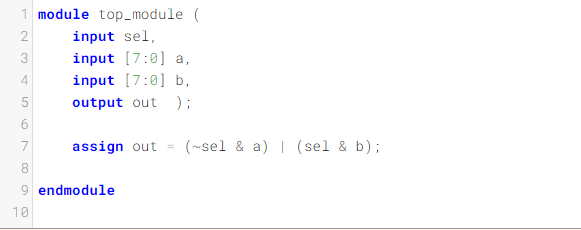
bit数不对,且表达式有问题。
module top_module ( input sel, input [7:0] a, input [7:0] b, output [7:0] out ); assign out = sel?a:b;endmodule3.1.2 NAND
这个三输入与非门不起作用。修复错误。
您必须使用提供的 5 输入与门:
module andgate ( output out, input a, input b, input c, input d, input e );

对应位置不对,且为与非。
module top_module (input a, input b, input c, output out); wire out_temp; andgate inst1 (.out(out_temp),.a(a),.b(b),.c(c),.d(1'b1),.e(1'b1)); assign out = ~out_temp;endmodule3.1.3 Mux
这个 4 对 1 多路复用器不起作用。修复错误。
为您提供了一个无错误的 2 对 1 多路复用器:
module mux2 ( input sel, input [7:0] a, input [7:0] b, output [7:0] out);
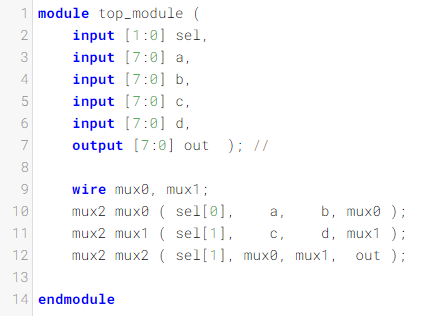
bit数不对,表达式有误。
module top_module ( input [1:0] sel, input [7:0] a, input [7:0] b, input [7:0] c, input [7:0] d, output [7:0] out ); wire [7:0] mux0, mux1; mux2 u1 ( sel[0], a, b, mux0 ); mux2 u2 ( sel[0], c, d, mux1 ); mux2 u3 ( sel[1], mux0, mux1, out );endmodule3.1.4 Add/Sub
以下带有零标志的加减法器不起作用。修复错误。
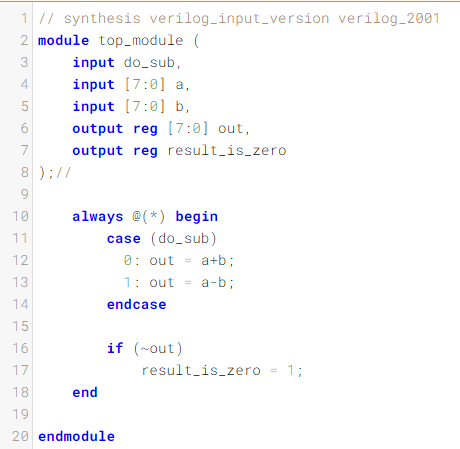
module top_module ( input do_sub, input [7:0] a, input [7:0] b, output reg [7:0] out, output reg result_is_zero); always @(*) begin case (do_sub) 0: out = a+b; 1: out = a-b; endcase if (out == 8'b0) result_is_zero = 1'b1; else result_is_zero = 1'b0; endendmodule3.1.5 Case Statement
该组合电路应该识别键 0 到 9 的 8 位键盘扫描码。它应该指示 10 种情况中的一种是否被识别(有效),如果是,则检测到哪个键。修复错误。
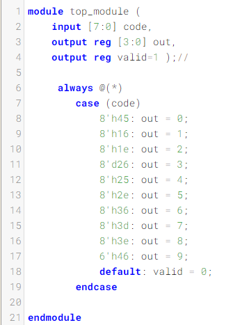
细小的错误,十进制,十六进制和二进制注意。
module top_module ( input [7:0] code, output reg [3:0] out, output reg valid ); always @(*)begin case (code) 8'h45: out = 0; 8'h16: out = 1; 8'h1e: out = 2; 8'h26: out = 3; 8'h25: out = 4; 8'h2e: out = 5; 8'h36: out = 6; 8'h3d: out = 7; 8'h3e: out = 8; 8'h46: out = 9; default: out = 0; endcase if((out == 0)&(code != 8'h45)) valid = 1'b0; else valid = 1'b1; endendmodule3.2 Build a circuit from a simulation wavefrom
3.2.1 combinational circuit 1
这是一个组合电路。阅读仿真波形以确定电路的作用,然后实现它。

module top_module ( input a, input b, output q ); assign q = a&b;endmodule3.2.2 combinational circuit 2
这是一个组合电路。阅读仿真波形以确定电路的作用,然后实现它。

module top_module ( input a, input b, input c, input d, output q ); assign q = (~a&~b&~c&~d)|(a&b&~c&~d)|(~a&b&~c&d)|(a&~b&~c&d)|(~a&~b&c&d)|(a&b&c&d)|(~a&b&c&~d)|(a&~b&c&~d);endmodule3.2.3 combinational circuit 3
这是一个组合电路。阅读仿真波形以确定电路的作用,然后实现它。

module top_module ( input a, input b, input c, input d, output q ); assign q = (b&d)|(a&d)|(b&c)|(a&c);endmodule3.2.4 combinational circuit 4
这是一个组合电路。阅读仿真波形以确定电路的作用,然后实现它。

module top_module ( input a, input b, input c, input d, output q ); assign q = b|c;endmodule3.2.5 combinational circuit 5
这是一个组合电路。阅读仿真波形以确定电路的作用,然后实现它。
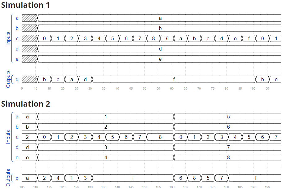
module top_module ( input [3:0] a, input [3:0] b, input [3:0] c, input [3:0] d, input [3:0] e, output [3:0] q ); always @(*) begin case(c) 4'b0000: q = b; 4'b0001: q = e; 4'b0010: q = a; 4'b0011: q = d; default q = 4'b1111; endcase endendmodule3.2.6 combinational circuit 6
这是一个组合电路。阅读仿真波形以确定电路的作用,然后实现它。

module top_module ( input [2:0] a, output [15:0] q ); always @(*) begin case(a) 3'b000: q = 16'h1232; 3'b001: q = 16'haee0; 3'b010: q = 16'h27d4; 3'b011: q = 16'h5a0e; 3'b100: q = 16'h2066; 3'b101: q = 16'h64ce; 3'b110: q = 16'hc526; 3'b111: q = 16'h2f19; endcase endendmodule3.2.7 Sequential cricuit 7
这是一个时序电路。阅读仿真波形以确定电路的作用,然后实现它。

module top_module ( input clk, input a, output q ); always @(posedge clk) begin if(a) q <= 1'b0; else q <= 1'b1; endendmodule3.2.8 Sequential cricuit 8
这是一个时序电路。阅读仿真波形以确定电路的作用,然后实现它。

module top_module ( input clock, input a, output p, output q ); assign p = clock?a:p; always @(negedge clock) begin q <= p; endendmodule3.2.9 Sequential cricuit 9
这是一个时序电路。阅读仿真波形以确定电路的作用,然后实现它。

module top_module ( input clk, input a, output [3:0] q ); always @(posedge clk) begin if(a) begin q <= 4'd4; end else if(q>=4'd6) begin q <= 4'd0; end else q <= q+1'b1; end endmodule3.2.10 Sequential cricuit 10
这是一个时序电路。该电路由组合逻辑和一位存储器(即一个触发器)组成。触发器的输出可以通过输出状态观察到。
阅读仿真波形以确定电路的作用,然后实现它。
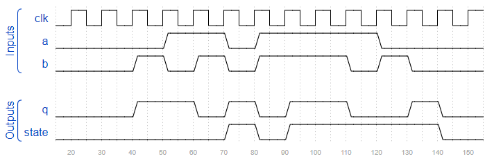
module top_module ( input clk, input a, input b, output q, output state ); assign q = a^b^state; always @(posedge clk) begin if(a&b) begin state <= 1'b1; end else if(~a&~b) begin state <= 1'b0; end else state <= state; endendmodule4.Verification: Writing Testbenches
4.1 Clock
为您提供了一个具有以下声明的模块:
module dut ( input clk ) ;
编写一个测试平台,创建一个模块dut实例(具有任何实例名称),并创建一个时钟信号来驱动模块的clk输入。时钟的周期为 10 ps。时钟应初始化为零,其第一次转换为 0 到 1。

module top_module ( ); reg clk; initial begin clk = 1'b0; end always #5 clk = ~clk; dut u1 (.clk(clk));endmodule4.2 Testbench1
创建一个 Verilog 测试平台,它将为输出 A 和 B 生成以下波形:

module top_module ( output reg A, output reg B ); initial begin A = 1'b0; B = 1'b0; #10 A = 1'b1; #5 B = 1'b1; #5 A = 1'b0; #20 B = 1'b0; endendmodule4.3 AND gate
您将获得以下要测试的 AND 门:
module andgate ( input [1:0] in, output out);
通过生成以下时序图,编写一个实例化此 AND 门并测试所有 4 个输入组合的测试平台:
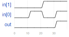
module top_module(); reg in_0,in_1; reg out; initial begin in_0 = 1'b0; in_1 = 1'b0; #10 in_0 = 1'b1; #10 in_0 = 1'b0; in_1 = 1'b1; #10 in_0 = 1'b1; end andgate u1 (.in({in_1,in_0}),.out(out));endmodule4.4 Testbench2
下面的波形设置了clk、in和s:

模块q7具有以下声明:
module q7 ( input clk, input in, input [2:0] s, output out);
编写一个测试平台,实例化模块q7并生成这些输入信号,如上图所示。
module top_module(); reg clk,in; reg [2:0] s; reg out; initial begin clk = 1'b0; in = 1'b0; s = 3'b010; #10 s = 3'b110; #10 in = 1'b1; s = 3'b010; #10 in = 1'b0; s = 3'b111; #10 in = 1'b1; s = 3'b000; #30 in = 1'b0; end always #5 clk = ~clk; q7 u1 (.clk(clk),.in(in),.s(s),.out(out));endmodule4.5 T flip-flop
给定一个 T 触发器模块,其声明如下:
module tff ( input clk, input reset, // active-high synchronous reset input t, // toggle output q);
编写一个实例化一个tff并重置 T 触发器然后将其切换到“1”状态的测试台。
module top_module (); reg clk,reset,t,q; initial begin clk = 1'b0; reset = 1'b0; t = 1'b0; #6 reset =1'b1; #12 reset = 1'b0; end always #5 clk = ~clk; always @(posedge clk) begin if(reset) t <= 1'b1; else t <= 1'b0; end tff u1 (.clk(clk),.reset(reset),.t(t),.q(q));endmodule